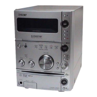
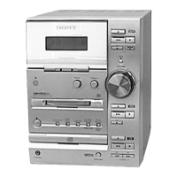
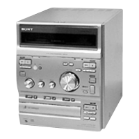
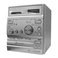
HCD-CP500K/CP500MD
4141
31
µ
s
3.4Vp-p
1.3Vp-p
0.2Vp-p
1.6Vp-p
3.5Vp-p
176.4kHz
231 ns
4 Vp-p
3.4 Vp-p
100 ns
4.4 Vp-p
63 ns
1
IC101 us XTAO
VOLT/DIV : 1V AC
TIME/DIV : 20 nsec
4.6 Vp-p
30 ns
2
IC1001 w; XOUT
VOLT/DIV : 1V AC
TIME/DIV : 40 nsec
3
IC309 qf X-O
VOLT/DIV : 1V AC
TIME/DIV : 100 nsec
4
IC306 qa XCOUT
VOLT/DIV : 1V AC
TIME/DIV : 20
µ
sec
5
IC306 qd XOUT
VOLT/DIV : 1V AC
TIME/DIV : 40 nsec
7
IC101 ef (FE)
(Play mode)
8
IC101 wh (TE)
(Play mode)
9
IC151 o; (FS4)
6
IC101 ek (RF)
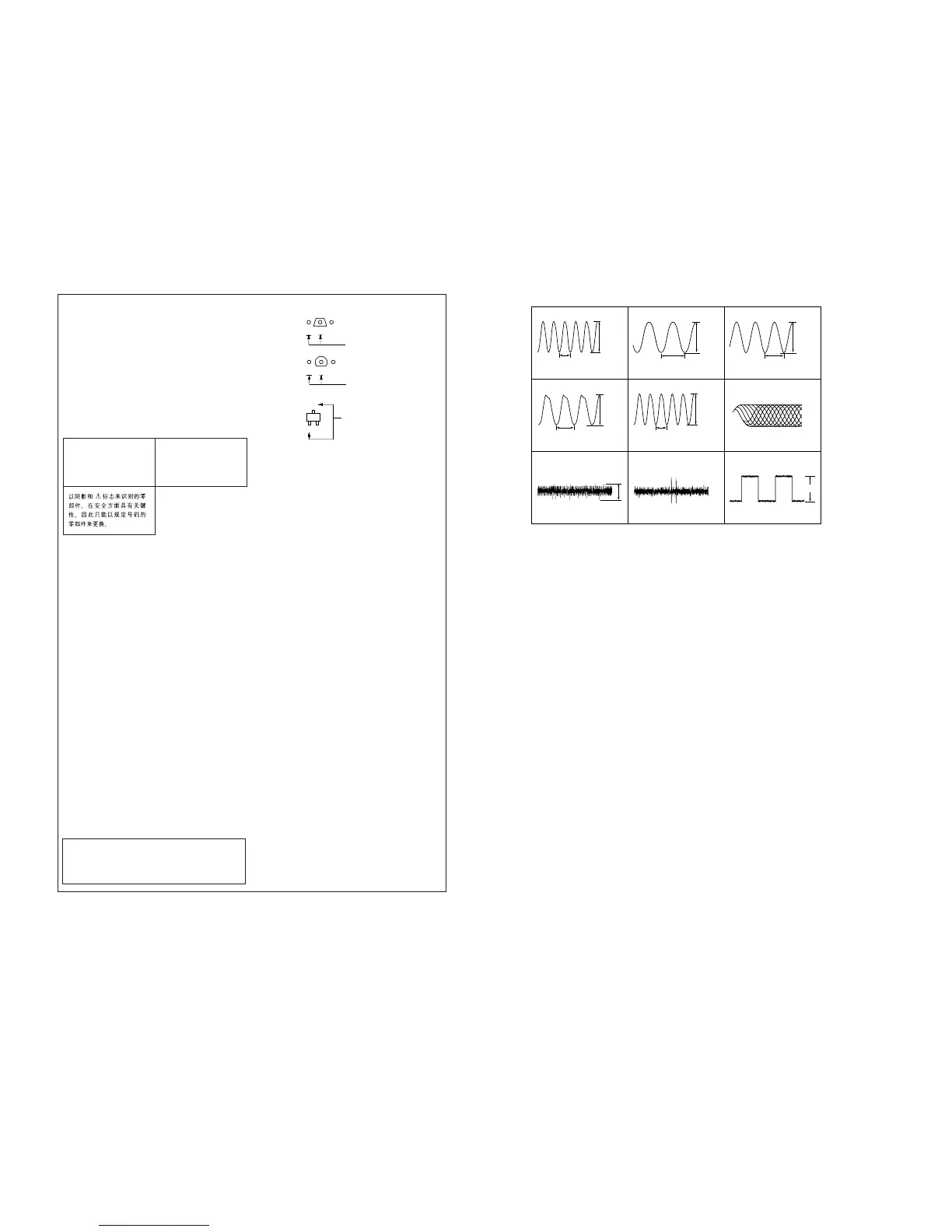
• Waveforms
THIS NOTE IS COMMON FOR PRINTED WIRING
BOARDS AND SCHEMATIC DIAGRAMS.
(In addition to this, the necessary note is printed
in each block.)
For schematic diagrams.
Note:
• All capacitors are in µF unless otherwise noted. pF: µµF
50 WV or less are not indicated except for electrolytics
and tantalums.
• All resistors are in Ω and
1
/
4
W or less unless otherwise
specified.
•
f
: internal component.
• 2 : nonflammable resistor.
• 1 : fusible resistor.
• C : panel designation.
For printed wiring boards.
Note:
• X : parts extracted from the component side.
• Y : parts extracted from the conductor side.
•
a
: Through hole.
• b : Pattern from the side which enables seeing.
(The other layers' patterns are not indicated.)
• A : B+ Line.
• B : B– Line.
• H : adjustment for repair.
• Voltages and waveforms are dc with respect to ground
under no-signal (detuned) conditions.
• Voltages are taken with a VOM (Input impedance 10 MΩ).
Voltage variations may be noted due to normal produc-
tion tolerances.
• Waveforms are taken with a oscilloscope.
Voltage variations may be noted due to normal produc-
tion tolerances.
• Circled numbers refer to waveforms.
• Signal path.
F : FM
g : VIDEO/MD (AUDIO)
E : PB (TAPE)
a : REC (TAPE)
J : CD (Analog)
c : CD (DIGITAL OUT)
p : MD (PB)
l : MD (REC)
• Abbreviation
AUS : Australian model
CH : Chinese model
E51 : Chilean and Peruvian model
HK : Hong Kong model
TH : Thai model
TW : Taiwan model
Caution:
Pattern face side: Parts on the pattern face side seen from the
(Side B) pattern face are indicated.
Parts face side: Parts on the parts face side seen from the
(Side A) parts face are indicated.
• Indication of transistor
C
B
These are omitted.
E
Q
B
These are omitted.
CE
B
These are omitted.
CE
Note:
The components identified by
mark ! or dotted line with mark
! are critical for safety.
Replace only with part number
specified.
Note:
Les composants identifiés par
une marque ! sont critiques
pour la sécurité.
Ne les remplacer que par une
pièce portant le numéro spécifié.


 To Next Page