Do you have a question about the Sony HCD-GN770 and is the answer not in the manual?
Details power output and total harmonic distortion for MHC-GX9000 USA model.
Specifies total harmonic distortion for MHC-GX9000 and MHC-GN770.
Lists power output and measurements for MHC-GN770 Mexican and other models.
Lists power output and measurements for MHC-GN660 Mexican and other models.
Specifies DIN power output and impedance for various models.
Lists continuous RMS power output with 10% THD for different models.
Details input specifications for VIDEO/MD, GAME, and MIC jacks.
Details output specifications for VIDEO OUT and PHONES jacks.
Provides approximate physical dimensions for the HCD models.
Lists approximate mass for HCD-GN770, GX9000, and GN660.
Lists items included with the unit, such as remote control and antennas.
Procedure for performing safety checks after service.
Details AC leakage testing procedures and limits for safety.
Specifies the wavelength for the optical CD digital output.
Specifies the output level for the optical CD digital output.
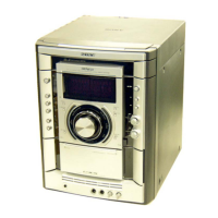
Location of controls on the main unit.
Provides a flow chart and detailed steps for unit disassembly.
Enables checking of various unit operations.
Procedures for adjusting mechanical components.
Procedures for adjusting electrical sections.
Highlights critical components that require specific replacement parts.
Precautions for handling the optical pick-up block to prevent electrostatic damage.
Instructions for safely checking the laser diode emission.
Procedure for checking laser diode and focus search operation.
Indicates the location of model identification on the back panel.
Identifies the location of controls on the main unit.
Lists buttons on the main unit with their reference pages.
Explains symbols used for controls on the main unit.
Lists remote control buttons and their functions.
Explains symbols used for remote control buttons.
Provides a visual flow chart for the disassembly process.
Details the procedure for removing the case, including screws.
Details the removal of the loading panel assembly.
Details the removal of the front panel assembly and its connections.
Details the removal of the CD mechanism deck and its wiring.
Details removal of tape mechanism deck and game board.
Details removal of CD switch board and panel board.
Details the removal of the switch board.
Details the removal of the tuner pack.
Details the removal of the primary board and its connectors.
Details the removal of the rear panel and its fan.
Details the removal of the main board and its connectors.
Details the removal of surround and PA boards and their connections.
Details the removal of the power transformer and its connectors.
Details the removal of the driver and SW boards and their connectors.
Details the disassembly of the BD board and optical pick-up.
Details the removal of the sensor board and its components.
Details the disassembly of the motor (TB) board.
Details the disassembly of the motor (LD) board.
Procedure to check fluorescent tube, LEDs, model, version, volume, etc.
Checks amplifier GEQ and volume control operations.
Details tape function checks, including ALC and rewind.
Procedure for testing the AMS function on tape decks.
Mode to check Amplifier, Tuner, and Tape operations.
Procedure to perform a cold reset, clearing all data.
Mode to switch the VACS system on or off.
Procedure to change AM channel step interval.
Mode for moving the CD sled motor freely for cleaning.
Mode for operation check of the CD section.
Displays error codes for mechanical and no-disc errors.
Enables CD playback to repeat for limitless times.
Moves optical pick-up and clears RAM data for customer return.
Moves optical pick-up to vibration-durable position.
Switches power supply to BU on/off during TUNER function.
Locks the disc trays, preventing them from opening.
Switches between VIDEO and MD modes.
Precautions for mechanical adjustments, including cleaning and tool usage.
Details torque measurements for various modes (FWD, REV, FF/REW).
Details adjustments for the deck section.
Procedure for adjusting head azimuth for decks A and B.
Notes for CD section adjustments, including waveform checks.
Details oscilloscope connection for S-curve check.
Shows the expected S-curve waveform and measurement points.
Oscilloscope connection for RFAC level check.
Displays the RFAC signal waveform and its level.
Oscilloscope connection for E-F balance check.
Displays traverse waveform with measurement points A, B, C.
Diagram showing test points on the CD board (Side B).
Notes on capacitor, resistor, and fusible resistor symbols.
Notes on identifying parts and patterns on printed wiring boards.
Lists abbreviations used for model regions and terms.
Diagram showing the physical location of various circuit boards.
Displays waveforms for IC401 and T101 on the main board.
Displays waveforms for IC101 on the BD board.
Displays waveforms for IC901, IC101, and T101.
Block diagram illustrating the CD section's signal flow.
Block diagram showing tuner and tape section signal paths.
Block diagram illustrating main section signal flow.
Block diagram showing display and power control sections.
Shows the layout of components and traces on the BD board.
Detailed schematic diagram of the BD board.
Shows component layout for Motor (LD), Driver, Motor (TB), Sensor, SW boards.
Schematic diagrams for Motor (LD), Driver, Sensor, Motor (TB), SW boards.
Shows the layout of components on the main board.
Detailed schematic of main board, covering IC301 and IC401 connections.
Detailed schematic of main board, covering IC600 and power amplifier.
Detailed schematic of main board, covering power supply and control signals.
Shows component layouts for CD SW, Jog, Game, and Switch boards.
Schematic diagrams for Game, Jog, CD-SW, and Switch boards.
Shows the component layout of the PA board.
Detailed schematic diagram of the PA board, including power amplifier.
Shows the component layout of the panel board (Part 1).
Shows the component layout of the panel board (Part 2).
Shows the component layout of the panel board.
Shows the component layout of the primary board.
Schematic diagram of the primary board, detailing power supply.
Schematic diagram of the surround board.
Shows the component layout of the surround board.
Block diagram for IC701 and IC712 on the driver board.
Block diagram for IC251 and IC301 on the BD board.
Detailed pin function description for IC101 on the BD board.
Detailed pin function description for IC301 on the BD board.
Continues pin function description for IC301.
Pin function details for IC901 on the panel board.
Pin function details for IC401 on the main board.
Continues pin function details for IC401 on the main board.
Notes regarding part standardization, stocking, and supply.
Lists abbreviations for model regions.
Exploded view of the case and rear panel assembly with part numbers.
Exploded view of the front panel assembly with part numbers.
Exploded view of the chassis section with part numbers.
Exploded view of the CD mechanism deck section 1 with part numbers.
Exploded view of the CD mechanism deck section 2 with part numbers.
Notes on part standardization and semiconductors.
List of capacitors with part numbers, descriptions, and specifications.
List of semiconductors with part numbers and descriptions.
Lists abbreviations for model regions and terms.
List of resistors with part numbers and specifications.
List of transistors with part numbers and specifications.
List of switches with part numbers.
List of vibrator components.
List of diodes with part numbers and specifications.
List of connectors with part numbers.
List of diodes with part numbers.
List of earth terminal components.
List of ICs with part numbers.
List of resistors with part numbers.
List of capacitors with part numbers.
List of variable resistors.
List of switches with part numbers.
List of capacitors with part numbers.
List of relays.
List of thermistors.
List of terminal boards.
List of connectors.
List of diodes with part numbers.
List of capacitors with part numbers.
List of connectors with part numbers.
List of diodes with part numbers.
List of ferrite beads.
List of ICs with part numbers.
List of transistors with part numbers.
List of short circuit components.
List of connectors.
List of transistors with part numbers.
List of capacitors with part numbers.
List of resistors with part numbers and specifications.
List of resistors with part numbers and specifications.
List of resistors with part numbers and specifications.
List of transistors with part numbers.
List of relays.
List of thermistors.
List of terminal boards.
List of connectors.
List of diodes with part numbers.
List of earth terminals.
List of resistors with part numbers and specifications.
List of transistors with part numbers.
List of resistors with part numbers and specifications.
List of switches with part numbers.
List of vibrator components.
List of capacitors with part numbers.
List of connectors.
List of diodes with part numbers.
List of connectors.
List of diodes with part numbers.
List of ferrite beads.
List of ICs with part numbers.
List of transistors with part numbers.
List of resistors with part numbers.
List of resistors with part numbers and specifications.
List of switches with part numbers.
List of vibrator components.
List of capacitors with part numbers.
List of connectors.
List of diodes with part numbers.
Notes on the switch board.
List of resistors with part numbers and specifications.
List of rotary encoders.
Miscellaneous parts including adaptors and filters.
List of flat type wires.
List of mechanical deck parts.
List of fuses.
List of vacuum fluorescent displays.
List of motor assemblies.
List of motor assemblies.
List of DC fans.
List of rotary encoders.
List of power transformers.
Records the version and date of revisions made to the manual.
| Speaker Configuration | 2.0 |
|---|---|
| Audio Channels | 2 |
| CD Player | Yes |
| FM/AM Tuner | Yes |
| Tuner Bands | FM/AM |
| Bluetooth | No |
| Cassette Deck | Yes |
| Type | Mini HiFi System |