EasyManua.ls Logo

Sony HCD-GN600 Service Manual

Sony HCD-GN600
72 pages
To Next Page IconTo Next Page
Page #1 background imageLoading...
Page #1 background image
SERVICE MANUAL
Model Name Using Similar Mechanism NEW
CD
CD Mechanism Type CDM74-K6BD47S
Section
Base Unit Name BU-K6BD47S
Optical Pick-up Name KSM-213DCP
TAPE
Model Name Using Similar Mechanism HCD-XGR88
Section Tape Transport Mechanism Type CWM43RR23
MiNi Hi-Fi COMPONENT SYSTEM
E Model
HCD-GN600
Ver 1.0 2003.04
9-877-282-01 Sony Corporation
2003D0200-1 Home Audio Company
C 2003.04 Published by Sony Engineering Corporation
SPECIFICATIONS
HCD-GN600 is the amplifier, CD player,
tape deck and tuner section in MHC-
GN600.
– Continued on next page –
Amplifier section
The following are measured at AC 127V, 60 Hz (Mexican model only)
The following are measured at AC 120, 220, 240V50/60 Hz
(except Mexican model)
DIN power output (rated) 130 + 130 watts
(6 ohms at 1 kHz, DIN)
Continuous RMS power output (reference)
165 + 165 watts
(6 ohms at 1 kHz, 10% THD)
Inputs
GAME (VIDEO): 1 Vp-p, 75 ohms
(phono jack)
GAME (AUDIO): Voltage 250 mV,
(phono jacks) impedance 47 kilohms
MD/VIDEO (AUDIO) IN: voltage 450 mV/250 mV,
(phono jacks) impedance 47 kilohms
MIC: sensitivity 1 mV,
(phone jack) impedance 10 kilohms
Outputs
VIDEO OUT: max. output level 1 Vp-p,
(phono jacks) unbalanced, Sync.
negative load impedance 75 ohms
PHONES: accepts headphones of
(stereo mini jack) 8 ohms or more
FRONT SPEAKER: accepts impedance of 6 to
16 ohms
CD player section
System Compact disc and digital audio system
Laser Semiconductor laser
(λ=795nm)
Laser Output Max. 44.6 µW*
*This output is the value measured at a
distance of 200 mm from the objective lens
surface on the Optical Pick-up Block with 7
mm aperture.
Frequency response 2 Hz – 20 kHz (±0.5 dB)
Wave length 795 nm
CD OPTICAL DIGITAL OUT
(Square optical connector jack, rear panel)
Wave length 660 nm
Output Level –18 dBm
Tape player section
Recording system 4-track 2-channel stereo
Frequency response 50 – 13,000 Hz (±3 dB),
using Sony TYPE I cassette
w
w
w
.
x
i
a
o
y
u
1
6
3
.
c
o
m
Q
Q
3
7
6
3
1
5
1
5
0
9
9
2
8
9
4
2
9
8
T
E
L
1
3
9
4
2
2
9
6
5
1
3
9
9
2
8
9
4
2
9
8
0
5
1
5
1
3
6
7
3
Q
Q
TEL 13942296513 QQ 376315150 892498299
http://www.xiaoyu163.com
Question and Answer IconNeed help?

Do you have a question about the Sony HCD-GN600 and is the answer not in the manual?

Sony HCD-GN600 Specifications

General IconGeneral
TypeMini Hi-Fi System
Power Output100 W
Audio Channels2.0
CD PlayerYes
Cassette DeckYes
USB PlaybackNo
Remote ControlYes
Radio TunerAM/FM
Speakers2

Summary

SERVICE MANUAL

HCD-GN600 Specifications

Details amplifier, CD, tape, tuner sections, laser output, frequency response.

SECTION 1 SERVICING NOTES

Handling Optical Pick-up & Laser Diode

Precautions for handling optical pick-up and laser diode emission checks.

Model Identification

Details model variants and their part numbers.

SECTION 2 GENERAL

Main Unit Controls Overview

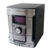
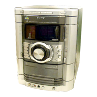
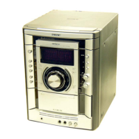
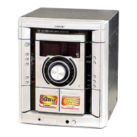
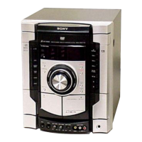
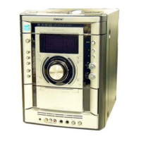
Overview of main unit controls and their functions.

Remote Control Functions

Remote Control Layout and Buttons

Diagram and list of remote control buttons and their functions.

SECTION 3 DISASSEMBLY

Disassembly Procedure Overview

Outlines the sequence for disassembling the set.

3-1. CASE Disassembly

3-2. LOADING (PANEL) Disassembly

3-3. FRONT PANEL ASSY Disassembly

3-4. TUNER PACK, SUB TRANS BOARD Disassembly

3-5. CD MECHANISM DECK Disassembly

3-6. GAME IN BOARD, TAPE MECHANISM DECK Disassembly

3-7. CD SWITCH BOARD, DISPLAY BOARD Disassembly

3-8. VOLUME BOARD Disassembly

3-9. REAR PANEL Disassembly

3-10. MAIN BOARD Disassembly

3-11. POWER AMP BOARD Disassembly

3-12. SW BOARD, DRIVER BOARD Disassembly

3-13. CD BOARD, CD BLOCK ASSY Disassembly

3-14. SENSOR BOARD Disassembly

3-15. MOTOR (TB) BOARD Disassembly

3-16. MOTOR (LD) BOARD Disassembly

SECTION 4 TEST MODE

GC Test Mode Operations

Checks fluorescent tube, LEDs, version, volume, key, VACS.

MC Test Mode Operations

Checks amplifier, tuner, and tape sections.

Cold Reset Procedure

Aging Mode Procedure

CD Error Code Mode

CD Repeat 5 Limit Off Mode

CD Ship Mode (Without Memory Clear)

CD Tray Lock Mode

SECTION 5 MECHANICAL ADJUSTMENTS

Torque Measurement

Specifies torque values for FWD, REV, FF/REW modes.

SECTION 6 ELECTRICAL ADJUSTMENTS

Record/Playback Head Azimuth Adjustment

Adjusts azimuth for optimal playback head alignment.

Record Bias Adjustment (Deck B)

Record Level Adjustment (Deck B)

CD Section S-curve Check

RFAC Level Check

E-F Balance Check

SECTION 7 DIAGRAMS

Circuit Board Location Overview

Shows the placement of all circuit boards within the unit.

7-1. CIRCUIT BOARD LOCATION

Waveforms

7-2. BLOCK DIAGRAM - CD SERVO Section

TUNER/TAPE DECK Section Diagram

MAIN/POWER Section Diagram

DISPLAY Section Diagram

7-3. PRINTED WIRING BOARD - CD Board

7-4. SCHEMATIC DIAGRAM - CD Board

7-5. PRINTED WIRING BOARDS - CD MECHANISM Board

7-6. SCHEMATIC DIAGRAM - CD MECHANISM Board

7-7. PRINTED WIRING BOARDS - MAIN Boards

7-8. SCHEMATIC DIAGRAM - MAIN Board (1/3)

7-9. SCHEMATIC DIAGRAM - MAIN Board (2/3)

7-10. SCHEMATIC DIAGRAM - MAIN (3/3) Boards

7-11. PRINTED WIRING BOARD - GAME IN, CD SWITCH Board

7-12. SCHEMATIC DIAGRAM - GAME IN, CD SWITCH Board

7-13. PRINTED WIRING BOARD - DISPLAY Board

7-14. SCHEMATIC DIAGRAM - DISPLAY BOARD

7-15. PRINTED WIRING BOARDS - POWER AMP Boards

7-16. SCHEMATIC DIAGRAM - POWER AMP Boards

7-17. PRINTED WIRING BOARDS - TRANS Board

7-18. SCHEMATIC DIAGRAM - TRANS Board

7-19. IC Block Diagrams

7-20. IC Pin Function Description

IC Pin Function Description (Continued)

IC Pin Function Description (IC501)

IC Pin Function Description (Continued)

IC Pin Function Description (IC601)

SECTION 8 EXPLODED VIEWS

8-1. CASE, REAR PANEL SECTION Exploded View

Exploded diagram of the case and rear panel assembly.

8-2. FRONT PANEL SECTION Exploded View

8-3. CHASSIS SECTION Exploded View

8-4. CD MECHANISM DECK SECTION-1 Exploded View

8-5. CD MECHANISM DECK SECTION-2 Exploded View

SECTION 9 ELECTRICAL PARTS LIST

Capacitors, Connectors, and Ferrite Beads List

List of capacitors, connectors, and ferrite beads with part numbers.

CD, CD SWITCH, DISPLAY Parts List

DISPLAY Parts List (Continued)

DISPLAY DRIVER Parts List

GAME IN MAIN Parts List

MAIN Parts List

MAIN Parts List (Continued)

POWER AMP Parts List

POWER AMP Parts List (Continued)

MOTOR (LD) MOTOR (TB) POWER AMP Parts List

POWER AMP, SENSOR, SUB TRANS Parts List

SUB TRANS SW TRANS VOLUME Parts List

VOLUME Parts List

REVISION HISTORY

Revision Log

Records changes made to the manual over time.

Related product manuals