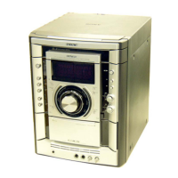
Do you have a question about the Sony HCD-GNX88 and is the answer not in the manual?
Technical specifications for the CD disc player, including laser output and frequency response.
Critical components identified by mark ▲ or dotted line require special attention.
Precautions for handling the optical pick-up block to prevent electrostatic discharge damage.
Guidelines for safely checking the laser diode emission from the optical pick-up block.
Procedure for checking laser diode and focus search operation using the S-curve check.
Outlines the step-by-step sequence for disassembling the unit.
Instructions for removing the side panels and top case of the unit.
Steps for removing the loading panel assembly, including disc tray manipulation.
Steps for removing the front panel assembly, including screws and connectors.
Instructions for removing the tuner pack module from the unit.
Procedures for removing the tape mechanism deck and the microphone board.
Steps to remove the panel board and the CD-SW board.
Instructions for removing the CD mechanism deck assembly.
Steps for detaching and removing the CDG board.
Procedures for removing the back panel, including screws and connectors.
Steps for detaching and removing the primary board.
Instructions for removing the power amplifier PC board and the main board.
Steps for detaching and removing the surround board and the PA board.
Instructions for removing the power transformer unit.
Steps for detaching and removing the driver board and the SW board.
Procedures for removing the BD84 board, including optical pick-up and springs.
Steps for detaching and removing the sensor board, including gears and belts.
Procedure to enter GC Test Mode for checking various indicators, versions, and levels.
Procedures for MC Test Mode to check Amplifier, Tuner, and Tape sections.
Procedure to perform a cold reset, clearing all preset data to initial conditions.
Mode to move the CD sled motor freely for cleaning the optical pick-up.
Mode for operation check of the CD section, performing aging operations.
Displays error codes when an error occurs in the CD section, indicating mechanical or no-disc errors.
Moves pick-up for vibration durability and clears preset data for returning to customer.
Precautions and settings for performing electrical adjustments on the deck section.
Procedure for adjusting the azimuth of the record/playback heads for optimal signal quality.
Detailed procedure for connecting an oscilloscope and performing the S-curve check for symmetry and peak levels.
Procedure to check the RFAC signal level and waveform shape for proper CD playback.
Procedure to check the E-F balance, including traverse waveform and servo control status.
| CD Player | Yes |
|---|---|
| Radio Tuner | Yes |
| Bluetooth | No |
| USB Playback | No |
| Remote Control | Yes |
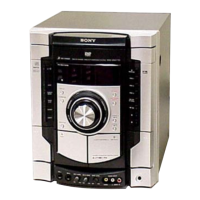
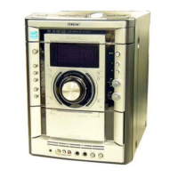
| Type | Mini HiFi System |
| Tuner Bands | FM/AM |
| Functions | CD, Radio, Cassette |
| Cassette Deck | Yes |