Do you have a question about the Sony HCD-GNX70 and is the answer not in the manual?
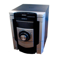
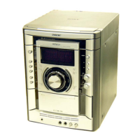
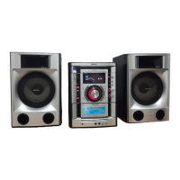
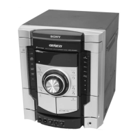
Lists component models for CD deck receiver and speaker systems.
Covers power requirements, consumption, dimensions, and mass.
Lists supplied accessories and defines abbreviations used.
Lists part numbers for accessories.
Initial release of the manual, marked as 'New'.
Specifies power output and total harmonic distortion for different models.
Details amplifier distortion, power outputs, and input/output specifications.
Covers disc player system, laser output, frequency response, and signal-to-noise ratio.
Provides general specs, power consumption, dimensions, and mass.
Outlines procedures for checking AC leakage from metal parts to earth ground.
Describes characteristics and handling of unleaded solder used in the product.
Advises on handling the optical pick-up block to prevent electrostatic breakdown.
Provides guidance on checking laser diode emission safely.
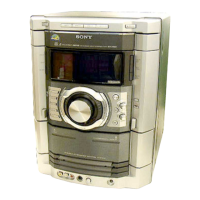
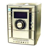
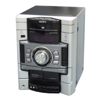
Shows how to identify the model and lists associated part numbers.
Lists button locations and reference pages for the main unit.
Identifies controls on the front and top panels of the unit.
Lists functions and page references for remote control buttons.
Explains the symbols used on the remote control for operations.
Outlines the sequence for disassembling the unit, referencing specific sections.
Details the procedure for removing the loading panel assembly.
Shows the procedure for disassembling and removing the tuner pack.
Illustrates the steps to remove the panel board and CD-SW board.
Details the procedure for disassembling the CD mechanism deck.
Details the procedure for removing the power amp PC board and main board.
Illustrates the procedure for removing the power transformer (T1200).
Illustrates the disassembly procedure for the CD board and its components.
Details the steps for removing the motor (TB) board.
Details GC Test Mode for checking indicators, keys, and levels.
Explains MC Test Mode for operations and Cold Reset for system initialization.
Describes modes for VACS control, tuner step change, and CD sled motor control.
Explains Aging Mode for CD checks and CD Power Manage for tuner reception.
Details CD error display mode and enables unlimited CD repeat playback.
Moves optical pick-up for durability and clears all preset data.
Covers CD ship mode without memory clear, tray lock, and video/MD input switching.
Disables remote commander reception to prevent disturbance during aging tests.
Provides precautions for cleaning, demagnetizing, and tool usage during adjustments.
Lists torque specifications for various mechanical adjustments.
States that CD block requires minimal adjustment and provides notes on cleaning the object lens.
Details the connection and procedure for performing an S-curve check on the CD board.
Explains how to connect an oscilloscope to check RFAC signal level.
Details the procedure for checking the E-F balance on the CD board.
Provides notes on component and pattern placement for printed wiring boards.
Explains symbols, abbreviations, and conventions used in schematic diagrams.
Shows a visual layout of the main boards like MAIN, CD, DRIVER, etc.
Highlights key ICs like IC101, IC301, IC303 and their interconnections within the CD section.
Shows the TC block, bias circuitry, and system control interface for the tape deck.
Shows the system control IC and signal paths connecting various sections like CD, Tape, and Tuner.
Covers speaker outputs, muting controls, and overload/thermal detection circuits.
Details the interface between system control, display controls, and the power supply transformer.
Highlights the positions of major ICs and components on the CD board.
Lists semiconductor components and their locations on the CD mechanism boards.
Lists semiconductor components and their locations on the main board.
Shows pin connections for the IC401 system control IC on the main board.
Illustrates power supply regulators and switching circuits on the main board.
Details audio processing ICs and output stage connections on the main board.
Lists semiconductor components and their locations on the panel board.
Highlights the positions of semiconductors on the CD-SW, Jog, and Mic boards.
Details IC pin functions and component values for the control boards.
Lists semiconductor components and their locations on the PA board.
Illustrates the power amplifier IC (STK412-150) and its associated output stage components.
Highlights the positions of components like transformers and regulators on the power boards.
Details the power supply circuitry, including transformer connections and voltage selector.
Shows waveforms for TEI, FEI, RFAC, and TAPE REC signals from the CD board.
Illustrates XC-OUT, X-OUT, TAPE REC waveforms and IC block diagrams.
Lists the pin names, I/O type, and descriptions for IC301.
Displays typical waveforms for RFAC, TEI, and FEI signals from the CD board.
Shows block diagrams for IC701/712 (Driver), IC904 (Panel), and IC251 (CD Board).
Lists pin numbers, names, I/O type, and descriptions for IC101.
Lists pin numbers, names, I/O type, and descriptions for IC101, pins 49-98.
Lists pin numbers, names, I/O type, and descriptions for IC101, pins 99-120.
Lists pin numbers, names, I/O type, and descriptions for IC401.
Lists pin numbers, names, I/O type, and descriptions for IC401, pins 20-49.
Lists pin numbers, names, I/O type, and descriptions for IC401, pins 50-100.
Lists pin numbers, names, I/O type, and descriptions for IC902.
Lists part numbers and descriptions for components shown in the exploded view.
Lists part numbers for components of the front panel assembly.
Lists part numbers for chassis components and boards.
Lists part numbers for components of the CD mechanism deck.
Lists part numbers for components of the CD mechanism deck.
Lists part numbers and descriptions for semiconductor components and coils used in the unit.
Defines abbreviations relevant to component specifications and types.
Lists part numbers for resistors used in the CD-SW and Driver sections.
Includes miscellaneous parts like adapters, tuners, and wiring harnesses in the parts list.
Details part numbers for keyboard switches and vibrator components on the Panel board.
Details part numbers for relays and thermistors used on the PA board.
Provides detailed listings of resistors and their specifications on the Main board.
Lists switches and vibrator components for the Main board.
Details part numbers for transistors and resistors on the PA board.
Details part numbers for capacitors and connectors on the Panel board.
Details part numbers for diodes and jumper resistors on the Panel board.
Lists miscellaneous parts like adapters, tuners, and wiring harnesses for various boards.
Details part numbers for Trans board components, fuses, relays, and switches.
Details part numbers for connectors, diodes, and fuses on the Primary board.
Lists miscellaneous items like adapters, tuners, wires, and motors for various boards.
Provides part numbers for wires, motors, fans, encoders, and power transformers.
Details changes made in version 1.1, including component and microprocessor updates.
Details speaker system type, units, impedance, dimensions, and mass for SS-RSX100.
Details speaker system type, units, impedance, dimensions, and mass for SS-RSX80.
Lists part numbers for the front panel, horn, screw, and loudspeaker components of the SS-RSX80.
Lists part numbers for the duct, front panel, horn, screw, and loudspeaker components of the SS-RSX100.
Initial release of the manual, marked as 'New'.
Details specifications for SS-GNX100 and SS-GNX60 speaker systems.
Details specifications for SS-GNX88 and SS-GNX66 magnetically shielded speaker systems.
Lists part numbers for duct, front panel, horn, screw, and loudspeaker components for SS-RSX speakers.
Initial release of the manual, marked as 'New'.
| Brand | Sony |
|---|---|
| Model | HCD-GNX70 |
| Category | Stereo System |
| Language | English |