EasyManua.ls Logo

Sony HCD-GNV111D Service Manual

Sony HCD-GNV111D
102 pages
To Next Page IconTo Next Page
Page #1 background imageLoading...
Page #1 background image
HCD-GNV99D/
GNV111D
E Model
HCD-GNV99D/GNV111D
Australian Model
HCD-GNV111D
SERVICE MANUAL
MiNi Hi-Fi COMPONENT SYSTEM
Sony Corporation
Audio Group
Published by Sony Engineering Corporation
9-879-585-02
2005E02-1
© 2005.05
SPECIFICATIONS
Ver.1.1 2005.05
– Continued on next page –
HCD-GNV99D/GNV111D are the Amplifier,
DVD player, tape deck and tuner
section in MHC-GNV99D/GNV111D.
DVD
Model Name Using Similar Mechanism NEW
DVD Mechanism Type CDM74H-DVBU101
Section
Optical Pick-up Name KHM-310CAB/C2NP
TAPE Model Name Using Similar Mechanism NEW
Section Tape Transport Mechanism Type CMAT2E2
Photo : HCD-GNV111D
Inputs
VIDEO INPUT: VIDEO: 1 Vp-p, 75 ohms
(phono jacks) AUDIO L/R: Voltage
250 mV, impedance 47 kilohms
TV/SAT AUDIO IN L/R: voltage 250 mV/450 mV,
(phono jacks) impedance 47 kilohms
MIC 1/2: sensitivity 1 mV,
(phone jack) impedance 10 kilohms
Outputs
AUDIO OUT: Voltage 250 mV
(phono jacks) impedance 1 kilohm
VIDEO OUT: max. output level 1 Vp-p,
(phono jack) unbalanced, Sync.
negative load impedance 75 ohms
COMPONENT VIDEO
OUT: Y: 1 Vp-p, 75 ohms
P
B
/C
B
: 0.7 Vp-p, 75 ohms
P
R
/C
R
: 0.7 Vp-p, 75 ohms
S VIDEO OUT: Y: 1 Vp-p, unbalanced,
(4-pin/mini-DIN jack) Sync. negative
C: 0.286 Vp-p load impedance 75 ohms
PHONES: accepts headphones of
(stereo mini jack) 8 ohms or more
FRONT SPEAKER: Use only the supplied speakers
SURR SPEAKER: Use only the supplied speakers
CENTER SPEAKER: Use only the supplied speaker
SUBWOOFER OUT: Voltage 250 mV
(phono jack) impedance 1 kilohm
Amplifier section
HCD-GNV111D
The following are measured at AC 120, 127, 220, 240V 50/60 Hz
DIN power output (rated)
Front speaker: 110 W + 110 W
(6 ohms at 1 kHz, DIN)
Center speaker: 50 W
(16 ohms at 1 kHz, DIN)
Surround speaker: 110 W + 110 W
(6 ohms at 1 kHz, DIN)
Continuous RMS power output (reference)
Front speaker: 160 W + 160 W
(6 ohms at 1 kHz, 10% THD)
Center speaker: 80 W
(16 ohms at 1 kHz, 10% THD)
Surround speaker: 160 W + 160 W
(6 ohms at 1 kHz, 10% THD)
HCD-GNV99D
The following are measured at AC 120, 127, 220, 240V 50/60 Hz
DIN power output (rated)
Front speaker: 130 W + 130 W
(6 ohms at 1 kHz, DIN)
Center speaker: 30 W
(8 ohms at 1 kHz, DIN)
Surround speaker: 30 W + 30 W
(8 ohms at 1 kHz, DIN)
Continuous RMS power output (reference)
Front speaker: 180 W + 180 W
(6 ohms at 1 kHz, 10% THD)
Center speaker: 50 W
(8 ohms at 1 kHz, 10% THD)
Surround speaker: 50 W + 50 W
(8 ohms at 1 kHz, 10% THD)

Table of Contents

Question and Answer IconNeed help?

Do you have a question about the Sony HCD-GNV111D and is the answer not in the manual?

Sony HCD-GNV111D Specifications

General IconGeneral
TypeMini Hi-Fi System
Audio Output ModeStereo
Remote ControlYes
FunctionsCD player, radio
Tuner BandsAM/FM
Speaker Output2 speakers

Summary

Amplifier Specifications

HCD-GNV111D Amplifier Specs

Amplifier specifications for HCD-GNV111D model.

HCD-GNV99D Amplifier Specs

Amplifier specifications for HCD-GNV99D model.

System Specifications Overview

Disc Player, Tape Deck, and Tuner Specs

Technical specifications for disc player, tape deck, and tuner sections.

General Unit Specifications

General specifications including power requirements and dimensions.

Servicing Notes and Model Information

Optical Pick-up and Laser Diode Handling

Precautions for handling the optical pick-up block and laser diode safely.

Self-Diagnosis Function and Error Codes

Explains the self-diagnosis function and error codes for troubleshooting.

DMB10 Board Replacement Note

Important note regarding DMB10 board replacement procedures.

Model Identification

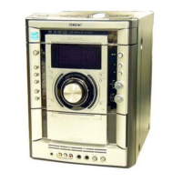
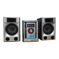
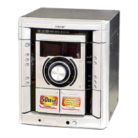
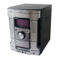
Identifies models and their corresponding part numbers for service.

General Unit Information and Controls

Locating Unit Controls

Guides users to find buttons and parts on the unit.

Button Location Index

Index of buttons and their corresponding reference pages for easy access.

Disassembly Procedures

Disassembly Flowchart

Provides a visual flowchart of the disassembly process.

Major Component Removal Steps

Details steps for removing case, panel, tuner, and mechanism components.

Test Mode Operations

GC and MC Test Mode Procedures

Details on entering and using GC/MC test modes for checks.

Special Test Modes (DVD/Video)

Covers DVD ship mode, tray lock, video/sat switching, and color system.

DVD Service Mode and IOP Measurement

Accesses diagnosis, adjustment menus, and IOP measurement.

Adjustments and Technical Diagrams

Mechanical and Electrical Adjustments

Covers mechanical adjustments, torque, electrical adjustments, and azimuth.

Block Diagrams by Section

Illustrates signal flow within RF, Video, Tape/Tuner, Main, AMP, and Display/Power sections.

Printed Wiring Boards and Schematics

Layouts and schematics for DMB10, CD mechanism, Main, Panel, MIC, PA, DVD SURR, and Video boards.

Waveform and IC Block Diagrams

Illustrates key waveforms and IC block diagrams for various circuits.

Exploded Views

Exploded Views of Major Assemblies

Provides exploded views for case, front panel, chassis, and DVD mechanism.

Electrical Parts List

Component Lists by Board

Lists electrical components for various boards like CD-SW, DMB10, and others.

Related product manuals