EasyManua.ls Logo

Sony HCD-GNZ77D Service Manual

Sony HCD-GNZ77D
60 pages
To Next Page IconTo Next Page
Page #1 background imageLoading...
Page #1 background image
1
Ver. 1.3 2007. 08
Model Name Using Similar Mechanism HCD-GNZ7D/GNZ8D/GNZ9D
DVD
DVD Mechanism Type CDM74HF-DVBU101//C
Section
Optical Pick-up Name KHM-310CAB/C2NP
Tape Deck
Model Name Using Similar Machanism NEW
Section
SERVICE MANUAL
E Model
HCD-GNZ77D/GNZ88D
Amplifier section
HCD-GNZ88D
The following measured at AC 120, 127, 220, 240 V,
50/60 Hz
DIN power output (rated)
75 W + 75 W
(4 ohms at 1 kHz, DIN)
Continuous RMS power output (reference)
Front speaker: 100 W + 100 W
(4 ohms at 1 kHz, 10%
THD)
Center speaker: 40 W (8 ohms at 1 kHz,
10% THD)
Surround speaker: 40 W + 40 W
(8 ohms at 1 kHz, 10%
THD)
HCD-GNZ77D
The following measured at AC 120, 127, 220, 240 V,
50/60 Hz
DIN power output (rated)
75 W + 75 W
(4 ohms at 1 kHz, DIN)
Continuous RMS power output (reference)
100 W + 100 W
(4 ohms at 1 kHz, 10%
THD)
Inputs
VIDEO INPUT (phono jacks):
VIDEO: 1 Vp-p, 75 ohms
AUDIO L/R: Voltage 250 mV,
impedance 47 kilohms
TV/SAT AUDIO IN L/R (phono jack):
Voltage 250 mV/450 mV,
impedance 47 kilohms
SPECIFICATIONS
Outputs
VIDEO OUT (phono jack):
max. output level
1 Vp-p, unbalanced, Sync
negative load impedance
75 ohms
COMPONENT VIDEO OUT:
Y: 1 Vp-p, 75 ohms
PB/CB: 0.7 Vp-p, 75 ohms
PR/CR: 0.7 Vp-p, 75 ohms
S-VIDEO OUT (4-pin/mini-DIN jack):
Y: 1 Vp-p, unbalanced,
Sync. negative
C: 0.286 Vp-p, load
impedance 75 ohms
PHONES (stereo mini jack):
Accepts headphones of
8 ohms or more
FRONT SPEAKER: Use only the supplied speakers
SURROUND SPEAKER (HCD-GNZ88D):
Use only the supplied speakers
CENTER SPEAKER (HCD-GNZ88D):
Use only the supplied speakers
SUB WOOFER OUT (phono jack):
Voltage 250 mV,
impedance 1 kilohm
Sony Corporation
Personal Audio Division
Published by Sony Techno Create Corporation
9-887-258-04
2007H04-1
© 2007. 08
– Continued on next page –
DVD DECK RECEIVER
(Photo: HCD-GNZ77D)
HCD-GNZ77D/GNZ88D are the
tuner, deck, DVD and amplifier
section in MHC-GNZ77D/GNZ88D.
w
w
w
.
x
i
a
o
y
u
1
6
3
.
c
o
m
Q
Q
3
7
6
3
1
5
1
5
0
9
9
2
8
9
4
2
9
8
T
E
L
1
3
9
4
2
2
9
6
5
1
3
9
9
2
8
9
4
2
9
8
0
5
1
5
1
3
6
7
3
Q
Q
TEL 13942296513 QQ 376315150 892498299
http://www.xiaoyu163.com
Question and Answer IconNeed help?

Do you have a question about the Sony HCD-GNZ77D and is the answer not in the manual?

Sony HCD-GNZ77D Specifications

General IconGeneral
TypeMini Hi-Fi System
Microphone InputYes
CD PlayerYes
Playable CD FormatsCD, CD-R, CD-RW
TunerFM/AM
Preset Stations30
Cassette DeckYes
Remote ControlYes
Audio Channels2.0
USB PlaybackYes
BluetoothNo
FunctionsCD, Tuner, USB
Audio Line IN/OUTYes
Speakers2

Summary

Service Manual HCD-GNZ77D/GNZ88D

Amplifier Section Specifications

Details power output and impedance for amplifier sections.

General Specifications

Lists output specifications for video, audio, and speaker connections.

Test Modes

Panel Test Mode Operations

Checks fluorescent tube, LEDs, buttons, volume jog, model, version, and VACS level.

Common Test Modes and Resets

Covers common test modes, cold reset, VACS control, and tuner step settings.

DVD and System Mode Functions

DVD Ship Modes and Service Functions

Procedures for DVD ship modes, service mode, firmware display, and tray lock.

System Function Modes

Includes TV/SAT switching, DVD color system, remote disable, and progressive modes.

DVD Service Diagnostics

Test Disc List and Service Mode Entry

Lists required discs and steps to enter DVD service mode.

IOP Measurement and Emergency History

Procedures for IOP measurement and checking the emergency history log.

Error Code Interpretation and Data Management

Understanding Error Codes and Parameters

Details the meaning of various error codes and their parameters.

Clearing System Data and History

Steps to clear laser hours, emergency history, and system setup data.

Mechanical Adjustments and Precautions

Version Information Check

Procedure to check system version information for main, sub, RISC, and other components.

Mechanical Adjustment Precautions

Important precautions before performing mechanical adjustments, including cleaning and tool usage.

Electrical Adjustments - DVD and Video

RFMON Level Check

Procedure to check the RFMON signal level on the DMB15 board using an oscilloscope.

Video Level Check

Adjustment for video signal level on the VIDEO BOARD to meet NTSC standards.

Deck Section Adjustments and Procedures

Record/Playback Head Azimuth Adjustment

Procedure for adjusting the azimuth of the record/playback heads for optimal performance.
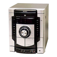
RF/Servo Section Block Diagram

Video Section Block Diagram

Main Section Block Diagram

Audio Section Block Diagram

Function and Power Block Diagram

Circuit Boards Location Overview

Waveform Illustrations and Parameters

Printed Wiring Boards - Driver Section Layout

Schematic Diagram - Driver Section Details

Printed Wiring Board - DMB15 Section (Side A) Layout

Printed Wiring Board - DMB15 Section (Side B) Layout

Schematic Diagram - DMB15 Section (1/5) Overview

Schematic Diagram - DMB15 Section (2/5) - DAC & Amps

Schematic Diagram - DMB15 Section (3/5) - Audio Outputs

Schematic Diagram - DMB15 Section (4/5) - Drivers

Schematic Diagram - DMB15 Section (5/5) - Memory

Deck Section Adjustments and Procedures

Printed Wiring Board - Volume Control Section

Printed Wiring Board - Microphone Input Section

Schematic Diagram - Microphone Input Section

Printed Wiring Board - Karaoke Function Section

Schematic Diagram - Karaoke Function Section

Printed Wiring Board - Video Output Section

Schematic Diagram - Video Output Section

Printed Wiring Board - Speaker Output Section

Schematic Diagram - Speaker Output Section

Schematic Diagram - Power Supply Section (HCD-GNZ88D)

Key Integrated Circuit (IC) Block Diagrams

IC Pin Descriptions - IC102 (RF, Servo, DVD)

IC Pin Descriptions - IC102 (Continued)

IC Pin Descriptions - IC102 (Continued)

IC Pin Descriptions - IC102 (Continued)

IC Pin Descriptions - IC102 (Continued)

IC Pin Descriptions - IC401 (System Control)

IC Pin Descriptions - IC401 (System Control) (Continued)

IC Pin Descriptions - IC401 (System Control) (Continued)

IC Pin Descriptions - IC403 (Signal In/Out Control)

Related product manuals