Do you have a question about the Sony HCD-GNZ88D and is the answer not in the manual?
Checks fluorescent tube, LEDs, keys, volume, model, destination, software version.
Checks Amplifier and Tape sections for operations.
Resets all data including preset data stored in RAM to initial conditions.
Clears data, moves optical pick-up to position durable to vibration.
Enables diagnosis and adjustment using remote commander and TV.
Verifies system firmware versions like Main, Sub, RISC, and Audio DSP.
Details torque specifications for FWD, REV, FF/REW, and tension adjustments.
Adjustments for DVD playback functionality and optical pick-up measurement.
Adjustments for video output signals and color system.
Verifies the RF signal level from the DMB15 board.
Shows system block diagrams for RF/Servo, Video, Main, Audio, and Power sections.
Illustrates PCB layouts for various sections like Driver, Panel, Mic, and Karaoke.
Displays expected signal waveforms for troubleshooting on DMB15, S-Master, and ADC boards.
Detailed electrical schematics for Driver, DMB15, MIC, Video, and Speaker sections.
Provides detailed pin assignments and descriptions for key integrated circuits.
| Brand | Sony |
|---|---|
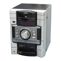
| Model | HCD-GNZ88D |
| Category | Stereo System |
| CD Player | Yes |
| Playable CD Formats | CD, CD-R, CD-RW |
| Tuner | Yes |
| FM Radio | Yes |
| AM Radio | Yes |
| Preset Stations | 30 |
| USB Port | Yes |
| Bluetooth | No |
| Remote Control | Yes |
| Audio Line IN/OUT | Yes |
| Microphone Input | Yes |
| Cassette Deck | No |
| Speaker Size | 10 cm |
| RMS Output Power | 50W |
| Functions | CD, USB, Radio |
| Speaker Type | 2-Way |
| Type | Mini Hi-Fi Component System |