Do you have a question about the Sony HCD-GNX700 and is the answer not in the manual?
Guidance on handling the optical pick-up block to prevent electrostatic breakdown and damage.
Procedures for checking laser diode emission and focus search operation.
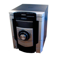
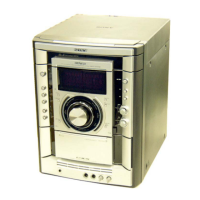
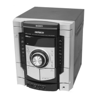
Details on identifying different models based on their back panel.
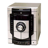
Overview of controls and their locations on the main unit, including top and front panels.
Description of buttons on the remote control and instructions for setting the clock.
A sequential guide illustrating the order of disassembly for various set components.
Step-by-step instructions for removing the side panels and top case.
Procedure for removing the loading panel, including pulley and disc tray.
Instructions for detaching the front panel assembly, including connectors and wires.
Procedure for removing the tuner pack, including its connection and mounting screws.
Steps to remove the tape mechanism deck and the associated MIC board.
Instructions for detaching the CD-SW board and the panel board.
Procedure for removing the function board and the jog board assembly.
Steps to detach the CD mechanism deck from the main unit.
Instructions for removing the back panel, including connectors and wires.
Procedure for removing the primary board and the effector board.
Steps to detach the power amplifier PC board assembly and the main board.
Instructions for removing the surround board and the PA board.
Procedure for removing the power transformer (T1200).
Steps to detach the driver board and the SW board.
Instructions for removing the CD board, including optical pick-up and coil springs.
Procedure for removing the sensor board, including tray, belt, and pulley.
Steps to detach the motor (TB) board and associated components.
Instructions for removing the motor (LD) board and loading motor assembly.
Checking fluorescent indicator tube, LEDs, jog dials, and software versions.
Checking amplifier, tuner, and tape operations; includes GEQ, volume, and tape recording checks.
Clears all data including preset data in RAM to initial conditions.
Switching the VACS (Variable Attenuation Control System) ON and OFF.
Toggling AM channel step interval between 9 kHz and 10 kHz.
Allows free movement of the CD sled motor for cleaning the optical pick-up.
Operation check mode for the CD section to verify aging operations.
Displays error codes related to mechanical and disc errors.
Enables CD playback to repeat for limitless times.
Moves optical pick-up for vibration durability and clears RAM data.
Moves optical pick-up for vibration durability without clearing RAM data.
Switches power supply to the BU during TUNER function ON or OFF.
Activates mode to prevent disc trays from opening via buttons.
Mode to switch between VIDEO and MD functions.
Prevents automatic power-off when TCM is not connected.
Precautions for cleaning, demagnetizing, and using correct tools for adjustments.
Table detailing torque meter readings for FWD and FF/REW modes.
General precautions and settings for performing electrical adjustments.
Procedure for adjusting the azimuth of record/playback heads for both decks.
Procedure for checking the CD S-curve waveform for symmetry and peak level.
Procedure to check RFAC signal level and waveform clarity.
Procedure to check E-F balance by confirming DC voltage levels in traverse waveform.
Notes on component identification, voltage measurements, and signal paths.
Information on component side, pattern side, and unleaded solder usage.
Diagram showing the physical layout and names of all circuit boards within the unit.
Collection of block diagrams for CD, Tape/Tuner, Main, Amp, and Display/Power sections.
Layout diagrams for various boards including CD, CD Mechanism, MAIN, PANEL, etc.
Detailed schematic diagrams for CD, CD Mechanism, MAIN, PANEL, PA, SURROUND, EFFECTOR, and POWER sections.
Detailed pin descriptions for key integrated circuits used in the unit.
Exploded view detailing parts for the case and back panel.
Exploded view showing components of the front panel assembly.
Exploded view detailing buttons, indicators, and escutcheons for the front panel.
Exploded view illustrating the main chassis components and their arrangement.
Exploded view of the CD mechanism deck, showing motors, gears, and boards.
Exploded view of the CD mechanism deck, detailing parts like magnets, pulleys, and insulators.
Comprehensive list of capacitors used in the CD board with part numbers and specifications.
Comprehensive list of resistors used in the CD board with part numbers and specifications.
Parts lists categorized by board (CD-SW, DRIVER, EFFECTOR, etc.) and component type (IC, Transistor, Diode).
Parts lists for MAIN and MIC boards, including connectors, diodes, ICs, and resistors.
Parts lists for PA and PANEL boards, detailing resistors, transistors, and capacitors.
Parts lists for PRIMARY and SW boards, including capacitors, connectors, and diodes.
Parts lists for SENSOR and SURROUND boards, including ICs, transistors, resistors, and capacitors.
Parts lists for TRANS board, switches, connectors, diodes, transistors, resistors, and miscellaneous items.
| Type | Mini Hi-Fi Component System |
|---|---|
| Power Output | 100W |
| CD Player | Yes |
| Bluetooth | No |
| USB Port | No |
| Remote Control | Yes |
| Radio Tuner | AM/FM |
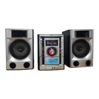
| Speaker Configuration | 2.0 |
| Functions | CD, Radio, Cassette |