EasyManua.ls Logo

Sony HCD-GN800 Service Manual

Sony HCD-GN800
76 pages
To Next Page IconTo Next Page
Page #1 background imageLoading...
Page #1 background image
SERVICE MANUAL
Model Name Using Similar Mechanism NEW
CD
CD Mechanism Type CDM74-K6BD47S
Section
Base Unit Name BU-K6BD47S
Optical Pick-up Name KSM-213DCP
TAPE
Model Name Using Similar Mechanism HCD-XGR88
Section Tape Transport Mechanism Type CWM43RR23
MiNi Hi-Fi COMPONENT SYSTEM
E Model
HCD-GN800
Ver 1.0 2003.04
9-877-275-01 Sony Corporation
2003D0200-1 Home Audio Company
C 2003.04 Published by Sony Engineering Corporation
SPECIFICATIONS
HCD-GN800 is the amplifier, CD player,
tape deck and tuner section in MHC-
GN800.
– Continued on next page –
Amplifier section
The following are measured at AC 127V, 60 Hz
(Mexican model only)
The following are measured at AC 120, 220, 240V
50/60 Hz (except Mexican model)
DIN power output (rated) 170 + 170 watts
(6 ohms at 1 kHz, DIN)
Continuous RMS power output (reference)
220 + 220 watts
(6 ohms at 1 kHz, 10% THD)
Inputs
GAME (VIDEO): 1 Vp-p, 75 ohms
(phono jack)
GAME (AUDIO): Voltage 250 mV,
(phono jacks) impedance 47 kilohms
MD/VIDEO (AUDIO) IN: voltage 450 mV/250 mV,
(phono jacks) impedance 47 kilohms
MIC: sensitivity 1 mV,
(phone jack) impedance 10 kilohms
Outputs
VIDEO OUT: max. output level 1 Vp-p,
(phono jacks) unbalanced, Sync.
negative load impedance 75 ohms
PHONES: accepts headphones of
(stereo mini jack) 8 ohms or more
FRONT SPEAKER: accepts impedance of 6 to 16 ohms
SURROUND SPEAKER: accepts impedance of 24 ohms or more
CD player section
System Compact disc and digital audio system
Laser Semiconductor laser
(λ=795nm)
Laser Output Max. 44.6 µW*
*This output is the value measured at a
distance of 200 mm from the objective
lens surface on the Optical Pick-up
Block with 7 mm aperture.
Frequency response 2 Hz – 20 kHz (±0.5 dB)
Wave length 795 nm
CD OPTICAL DIGITAL OUT
(Square optical connector jack, rear panel)
Wave length 660 nm
Output Level –18 dBm
Tape player section
Recording system 4-track 2-channel stereo
Frequency response 50 – 13,000 Hz (±3 dB), using Sony
TYPE I cassette

Table of Contents

Question and Answer IconNeed help?

Do you have a question about the Sony HCD-GN800 and is the answer not in the manual?

Sony HCD-GN800 Specifications

General IconGeneral
TypeMini Hi-Fi Component System
CD PlayerYes
FM/AM TunerYes
BluetoothNo
USB PlaybackNo
Cassette DeckYes
Remote ControlYes
FunctionsCD, Radio, Tape

Summary

SECTION 1 SERVICING NOTES

Optical Pick-up and Laser Diode Handling

Precautions for handling optical pick-up, laser diode, and static discharge.

Laser Diode Emission Check Procedure

Steps for checking laser diode emission and focus search operation.

SECTION 3 DISASSEMBLY

Case and Loading Panel Removal

Step-by-step guide for removing the outer case and loading panel assembly.

Front Panel Assembly Removal

Instructions for detaching the front panel assembly from the main unit.

CD Mechanism Deck Removal

Steps to detach the CD mechanism deck from the chassis.

Main Board Removal

Procedure for detaching the main control board from the chassis.

Power Amp Board Removal

Steps to remove the power amplifier board.

CD Board and CD Block Assy Removal

Process for removing the CD board and CD block assembly.

SECTION 4 TEST MODE

GC Test Mode Procedures

Mode for checking fluorescent indicator, LEDs, model, version, volume, and VACS.

MC Test Mode Procedures

Mode to check amplifier, tuner, and tape sections operations, including various checks like amplifier, clock, tape, AMS.

Cold Reset Procedure

Resets all data and initial conditions, clearing RAM.

CD Error Code Mode Display

Displays error codes when an error occurs in the CD section.

CD Ship Mode (With Memory Clear)

Moves optical pick-up and clears all data for customer return.

CD Ship Mode (Without Memory Clear)

Moves optical pick-up to a vibration-durable position for customer return.

SECTION 5 MECHANICAL ADJUSTMENTS

Mechanical Adjustment Precautions

General precautions to follow before performing mechanical adjustments.

Torque Measurement Procedures

Detailed procedures for measuring torque on various mechanical parts.

SECTION 6 ELECTRICAL ADJUSTMENTS

Deck Section Electrical Adjustments

General precautions and procedures for deck section electrical adjustments.

Head Azimuth Adjustment

Procedure for adjusting the azimuth of the record/playback heads for optimal audio.

Rec Bias Adjustment (Deck B)

Steps for adjusting the recording bias on tape deck B.

Rec Level Adjustment (Deck B)

Procedure for adjusting the recording level on tape deck B.

CD S-curve Check

Method to check the S-curve waveform for the CD player's focus servo.

RFAC Level Check

Procedure to check the RFAC signal level for the CD player.

E-F Balance Check

Procedure to check the E-F balance of the CD player's tracking and sledding servos.

SECTION 7 DIAGRAMS

IC Pin Function Description

Detailed pin descriptions for important ICs used in the unit.
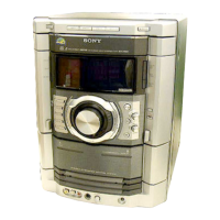
SECTION 8 EXPLODED VIEWS

SECTION 9 ELECTRICAL PARTS LIST

Related product manuals