EasyManua.ls Logo

Sony HCD-GN1100D Service Manual

Sony HCD-GN1100D
106 pages
To Next Page IconTo Next Page
Page #1 background imageLoading...
Page #1 background image
HCD-GN1100D
E Model
SERVICE MANUAL
MINI HI-FI COMPONENT SYSTEM
Sony Corporation
Personal Audio Division
Published by Sony Techno Create Corporation
9-887-683-03
2007J02-1
© 2007.10
SPECIFICATIONS
Ver. 1.2 2007.10
– Continued on next page –
HCD-GN1100D is the Amplifier,
DVD player, tape deck and tuner
section in MHC-GN1100D.
DVD
Model Name Using Similar Mechanism HCD-GN1000D
DVD Mechanism Type CDM74HF-DVBU101
Section
Optical Pick-up Name KHM-313CAB/C2NP
TAPE
Model Name Using Similar Mechanism HCD-GN1000D
Section
Tape Transport Mechanism Type CWN42RR603
Amplifier section
The following are measured at AC 120, 127, 220,
240V 50/60 Hz
Power output (rated): 130 W + 130 W
(6 , 1 kHz, 1% THD)
RMS output power (reference)
Front speaker: 215 W + 215 W
(per channel at 6 , 1 kHz, 10%
THD)
Center speaker: 85 W
(per channel at 6 , 1 kHz, 10%
THD)
Surround speaker: 90 W + 90 W
(per channel at 6 , 1 kHz, 10%
THD)
Subwoofer: 210 W (per channel at 8 Ω , at 100 Hz,
10% THD)
Inputs
VIDEO INPUT:
VIDEO: 1 Vp-p, 75 ohms
AUDIO L/R: Voltage 250 mV,
impedance 47 kilohms
TV/SAT AUDIO IN L/R:
Voltage 250 mV/450 mV, impedance
47 kilohms
MIC 1 or 2:
Sensitivity 1 mV, impedance
10 kilohms
Outputs
AUDIO OUT:
Voltage 250 mV, impedance 1 kilohm
VIDEO OUT:
Max. output level 1 Vp-p, unbalanced,
Sync. negative load impedance
75 ohms
COMPONENT VIDEO OUT:
Y: 1 Vp-p, 75 ohms
PB/CB: 0.7 Vp-p, 75 ohms
PR/CR: 0.7 Vp-p, 75 ohms
S VIDEO OUT:
Y: 1 Vp-p, unbalanced, Sync. negative
C: 0.286 Vp-p, load impedance
75 ohms
PHONES:
accepts headphones of 8 ohms or more
Disc player section
System
Compact disc and digital audio and
video system
Laser
Semiconductor laser (DVD: λ =650 nm,
CD: λ = 790 nm)
Emission duration: continuous
Frequency response
DVD (PCM 48 kHz): 2 Hz – 22 kHz
(±1 dB)
CD: 2 Hz – 20 kHz (±0.5 dB)
Video color system format
Latin American models: NTSC
Russian models: PAL
Other models: NTSC and PAL

Table of Contents

Question and Answer IconNeed help?

Do you have a question about the Sony HCD-GN1100D and is the answer not in the manual?

Sony HCD-GN1100D Specifications

General IconGeneral
CD PlayerYes
FM TunerYes
USB PlaybackYes
BluetoothNo
FunctionsCD, Radio, USB
Tuner BandsFM
Cassette DeckYes
AM TunerYes
Remote ControlYes
Speaker Configuration2.0
TypeMini System
Speaker Type2-way speaker
Power Output100 Watts
RMS Output Power50 Watts

Summary

Service Manual Introduction and Specifications

Specifications Overview

Details on Amplifier, Component Video, S Video, Phones, Disc Player System, Laser, Frequency response, and Video color system.

Tuner and General Specifications

Self-diagnosis Function and Display Messages

Covers self-diagnosis error codes and version number display on TV.

Servicing Notes and Handling Precautions

Optical Pick-up, Laser Diode, and Component Handling

Guidelines for safely handling optical pick-up blocks, laser diodes, and chip components.

Circuit Board Repair and Safety Warnings

Instructions for flexible circuit board repair and critical safety component replacement.

Unleaded Solder and Model Identification

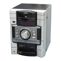
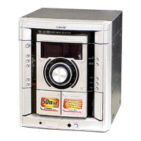
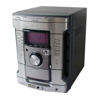
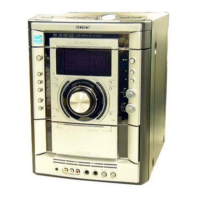
Information on unleaded solder characteristics and back panel model identification.

General Controls Overview

Front and Top Panel Control Identification

Detailed identification and function of controls on the front and top panels.

Remote Control Operation

Setting the System Clock

Procedure for setting the system clock using the remote control.

Disassembly Procedures

Disassembly Flow Chart

Visual representation of the step-by-step disassembly process.

Disassembly - Case and Loading Panel

Disassembly - Tuner Pack and DVD Mechanism

Disassembly - Front Panel and Tape Mechanism

Disassembly - CD-SW, Panel, Function, and Jog Boards

Disassembly - Karaoke, Video, DMB16 Boards, and Back Panel

Disassembly - Primary, Effectos, Power Amp, and Main Boards

Disassembly - Surround, PA Boards, and Power Transformer

Disassembly - Driver/SW Boards and DVD Assy

Disassembly - Optical Pick-up and Sensor Board

Disassembly - Motor (TB) and Motor (LD) Boards

Test Modes

Panel and Common Test Modes

Details on Panel Test Mode and Common Test Mode procedures.

Test Modes (Continued)

DVD Ship, Tray Lock, TV/SAT, Color System, and Remote Modes

Procedures for DVD Ship Mode, Tray Lock, TV/SAT switching, Color System, and Remote Disable.

Test Modes (DVD Specific)

DVD Service Mode and IOP Measurement

Instructions for DVD Service Mode and IOP measurement procedures.

Troubleshooting - Emergency History and Error Codes

Emergency History Check and Error Code Interpretation

Guide to checking emergency history and interpreting error codes.

System Maintenance and Error Handling

Clearing Setup Data, Firmware Check, and Error Messages

Procedures for clearing setup data, checking firmware, and handling error messages.

Mechanical Adjustments

Precaution and Torque Measurement

Precautions for mechanical adjustments and torque specifications.

Electrical Adjustments

Tuner Section and Head Azimuth Adjustment

Procedures for checking tuner sensitivity and head azimuth alignment.

Test Procedures and Waveform Checks

Test Disc List and RFMON Level Check

List of test discs and procedure for checking RFMON signal level.

Diagrams and Circuit Board Locations

Notes for Schematic and Printed Wiring Diagrams

General notes and symbols used in schematic and PWB diagrams.

Waveform Analysis

DMB16, Main, and Video Board Waveforms

Visual representations of key waveforms from various boards.

Block Diagrams - RF Section

Block Diagrams - Video Section

Block Diagrams - Tape and Tuner Section

Block Diagrams - Main Section

Block Diagrams - Amplifier Section

Block Diagrams - Display and Power Section

Printed Wiring Boards - DMB16 Board (Side A)

Printed Wiring Boards - DMB16 Board (Side B)

Schematic Diagrams - DMB16 Board (1/4)

Schematic Diagrams - DMB16 Board (2/4)

Schematic Diagrams - DMB16 Board (3/4)

Schematic Diagrams - DMB16 Board (4/4)

Printed Wiring Boards - CD Mechanism Boards

Schematic Diagrams - CD Mechanism Boards

Printed Wiring Boards - Main Board

Schematic Diagrams - Main Board (1/5)

Schematic Diagrams - Main Board (2/5)

Schematic Diagrams - Main Board (3/5)

Schematic Diagrams - Main Board (4/5)

Schematic Diagrams - Main Board (5/5)

Printed Wiring Boards - Panel Board

Schematic Diagrams - Panel Board

Printed Wiring Boards - CD-SW, JOG, Function, and MIC Boards

Schematic Diagrams - CD-SW, JOG, Function, and MIC Boards

Printed Wiring Boards - PA Board

Schematic Diagrams - PA Board

Printed Wiring Boards - Surround Board

Schematic Diagrams - Surround Board (1/2)

Schematic Diagrams - Surround Board (2/2)

Printed Wiring Boards - Effectos Board

Schematic Diagrams - Effectos Board

Printed Wiring Boards - Video Board

Schematic Diagrams - Video Board

Printed Wiring Boards - Power Section

Schematic Diagrams - Power Section

Printed Wiring Boards - Karaoke Board

Schematic Diagrams - Karaoke Board

IC Block Diagrams

DMB16 Board IC Block Diagrams

Block diagrams illustrating the function of ICs on the DMB16 board.

IC Pin Function Descriptions

IC102 Pin Function Description

Detailed pinout and function description for IC102 (CXD9849R).

IC Pin Function Descriptions (Continued)

IC401 Pin Function Description

Detailed pinout and function description for IC401 (MB90M407PF-G-150E1).

IC Pin Function Descriptions (Continued)

IC Pin Function Descriptions (Continued)

IC Pin Function Descriptions (Continued)

IC Pin Function Descriptions (Continued)

IC Pin Function Descriptions (Continued)

IC Pin Function Descriptions (Continued)

IC Pin Function Descriptions (Continued)

IC Pin Function Descriptions (Continued)

Exploded Views

Case and Back Panel Assembly

Exploded view illustrating the case and back panel components.

Exploded Views (Front Panel Part 1)

Exploded Views (Front Panel Part 2)

Exploded Views - Chassis Section

Exploded Views - DVD Mechanism Section 1

Exploded Views - DVD Mechanism Section 2

Electrical Parts List

CD-SW Board Parts

List of resistors, switches, and capacitors for the CD-SW board.

Electrical Parts List (Continued)

DMB16 Board Parts

List of capacitors, connectors, diodes, and terminals for the DMB16 board.

Electrical Parts List (Continued)

DMB16 Driver Board Parts

List of resistors and transistors for the DMB16 driver board.

Electrical Parts List (Continued)

Main Board Parts (Resistors)

List of resistors for the Main board.

Electrical Parts List (Continued)

Main Board (MIC Section) Parts

List of resistors, transistors, and ICs for the Main board MIC section.

Electrical Parts List (Continued)

Effectos and Function Board Parts

List of resistors, transistors, ICs, capacitors, and connectors for Effectos and Function boards.

Electrical Parts List (Continued)

JOG, Karaoke, and Main Board (Resistors) Parts

List of resistors for Jog, Karaoke, and Main boards.

Electrical Parts List (Continued)

Jog Board Parts

List of resistors, switches, capacitors, and jumpers for the Jog board.

Electrical Parts List (Continued)

Primary, Sensor Boards Parts

List of resistors, capacitors, connectors, diodes, ICs, and transistors for Primary and Sensor boards.

Electrical Parts List (Continued)

Main Board Parts (Capacitors)

List of capacitors for the Main board.

Electrical Parts List (Continued)

Main Board (MIC) and Connector Parts

List of transistors, diodes, ICs, connectors, and jumper resistors for the Main board.

Electrical Parts List (Continued)

Main Board Parts (Jumper Resistors, Coils, Transistors)

List of jumper resistors, coils, and transistors for the Main board.

Electrical Parts List (Continued)

Main Board Parts (Resistors)

List of resistors for the Main board.

Electrical Parts List (Continued)

Main Board Parts (Resistors Continued)

List of resistors for the Main board.

Electrical Parts List (Continued)

Main Board Parts (Resistors Continued)

List of resistors for the Main board.

Electrical Parts List (Continued)

Main Board (MIC) Parts (Resistors, Transistors)

List of resistors and transistors for the Main board MIC section.

Electrical Parts List (Continued)

Motor (LD/TB), PA Board, and Diode Parts

Parts list for Motor (LD/TB), PA board, and diodes.

Electrical Parts List (Continued)

PA Board Parts (Resistors, Transistors)

List of resistors and transistors for the PA board.

Electrical Parts List (Continued)

Panel Board Parts

List of resistors, capacitors, transistors, diodes, ICs, and connectors for the Panel board.

Electrical Parts List (Continued)

Video Board Parts and Miscellaneous

List of ICs, jacks, jumper resistors, and miscellaneous items for the Video board.

Electrical Parts List (Continued)

Surround, SW, Trans, Video Board Parts

Parts list for Surround, SW, Trans, and Video boards.

Electrical Parts List (Continued)

Surround, SW, Trans, Video Board Parts (Resistors, Transistors)

List of resistors and transistors for Surround, SW, Trans, and Video boards.

Electrical Parts List (Continued)

Surround, SW, Trans, Video Board Parts (Capacitors, Connectors, Diodes, Fuses)

List of capacitors, connectors, diodes, and fuses for Surround, SW, Trans, and Video boards.

Electrical Parts List (Continued)

Video Board Parts (ICs, Jacks, Jumpers, Resistors) and Miscellaneous

List of ICs, jacks, jumper resistors, and miscellaneous items for the Video board.

Related product manuals