— 15 —
BD board
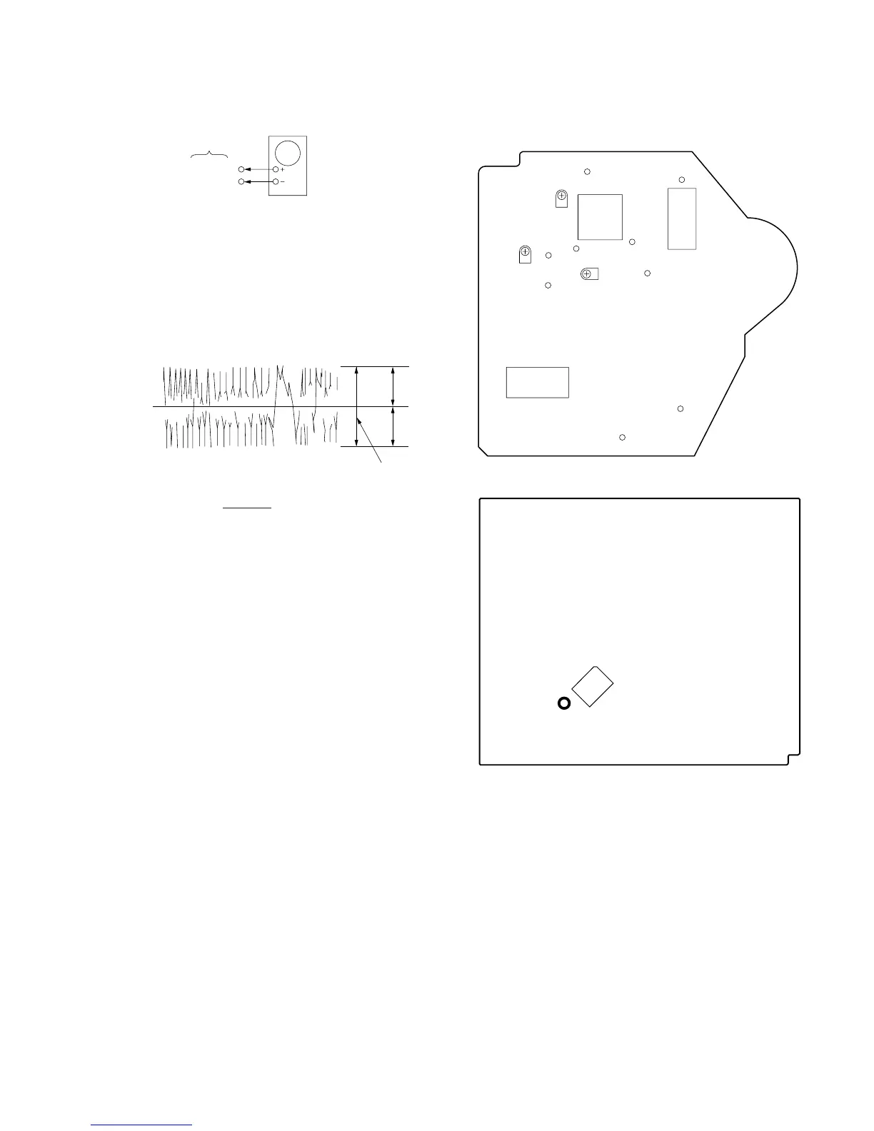
E-F Balance Check
oscilloscope
TP (TEO)
TP (VC)
Procedure:
1. Connect test point TP703 (ADJ2) on Main board to Ground with
a lead wire.
2. Connect oscilloscpe to test point TP (TEO).
3. Turned Power switch on.
4. Put disc (YEDS-18) in and playback.
5. Confirm that the oscilloscope waveform is symmetrical on the
top and bottom in relation to 0Vdc, and check this level.
Traverse waveform
A
B
level: 300 ± 100 mVp-p
0V
Specified level: • x 100 = less than ± 7%
• A + B = 300 ± 100 mVp-p
6. Remove the lead wire connected in step 1.
Focus/Tracking Gain Adjustment (RV102, RV103)
This gain has a margin, so even if it is slightly off.
There is no problem.
Therfore, do not perform this adjustment.
Please note that it should be fixed to mechanical center position
when you moved and do not know original position.
A – B
2 (A + B)
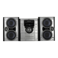
Adjustment Location:
[BD BOARD] — Component Side —
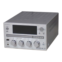
[MAIN BOARD] — Conductor Side —
IC701
TP703
(ADJ2)
IC104
GND
PCK
RF
RV101
IC101
FOK
RV102
TEO
FEO
TEI
FEI
VC
RV103
IC102