EasyManua.ls Logo

Sony HCD-GT555 Service Manual

Sony HCD-GT555
118 pages
To Next Page IconTo Next Page
Page #1 background imageLoading...
Page #1 background image
SERVICE MANUAL
Sony Corporation
Audio&Video Business Group
Published by Sony Techno Create Corporation
HCD-GT111/GT222/
GT444/GT555
SPECIFICATIONS
COMPACT DISC DECK RECEIVER
9-889-112-03
2008G05-1
©
2008.07
AEP Model
HCD-GT111/GT222/GT444
UK Model
HCD-GT444
E Model
Russian Model
HCD-GT111/GT222/GT444/GT555
Ver. 1.2 2008.07
HCD-GT111 is the ampli er, USB, CD player, tape
deck and tuner section in MHC-GT111/GT111BP.
HCD-GT222 is the ampli er, USB, CD player, tape
deck and tuner section in MHC-GT222.
HCD-GT444 is the ampli er, USB, CD player, tape
deck and tuner section in MHC-GT444.
HCD-GT555 is the ampli er, USB, CD player, tape
deck and tuner section in MHC-GT555.
Photo: HCD-GT555
CD
Section
Model Name Using Similar Mechanism
NEW
Mechanism Type
CDM88A-K6BD93-WOD
Optical Pick-up Block Name
KSM-213DCP
Tape deck
Section
Model Name Using Similar Mechanism
HCD-EC55/EC77
Tape Transport Mechanism Type
TCM-J1 or CS-21SC-900TP
Amplifier section
HCD-GT555
The following are measured at AC 120, 127,
220, 230 240 V 50/60 Hz
Front speaker
Power output (rated): 110 W + 110 W
(at 6 Ω, 1 kHz, 1% THD)
RMS output power (reference):
200W + 200 W (per channel at 6 Ω,
1kHz,10%THD)
Subwoofer
RMS output power (reference): 190 W
(at 6 Ω,100Hz,10%THD)
HCD-GT444
The following are measured at AC 120, 127,
220, 230 240 V 50/60 Hz
Front speaker
Power output (rated): 90 W + 90 W
(at 6 Ω, 1 kHz, 1% THD)
RMS output power (reference):
150 W + 150 W (per channel at 6 Ω,
1 kHz, 10% THD)
Subwoofer
RMS output power (reference): 150 W
(at 6 Ω, 100 Hz, 10% THD)
HCD-GT222
The following are measured at AC 120, 127,
220, 230 240V 50/60 Hz
Power output (rated): 110 W + 110 W
(at 6 Ω, 1 kHz, 1% THD)
RMS output power (reference):
200 W + 200 W (per channel at 6 Ω,
1 kHz, 10% THD)
HCD-GT111
The following are measured at AC 120, 127,
220, 230 240V 50/60 Hz
Power output (rated): 60 W + 60 W
(at 6 Ω, 1 kHz, 1% THD)
RMS output power (reference):
100 W + 100 W (per channel at 6 Ω,
1 kHz, 10% THD)
Inputs
AUDIO INPUT L/R : voltage
250 mV, impedance 47 kilohms
MIC: sensitivity 1 mV, impedance
10 kilohms
(USB) port: Type A
Outputs
PHONES: accepts headphones of 8 Ω or
more
FRONT SPEAKER: accepts impedance of
6 Ω
SUBWOOFER (HCD-GT555/
HCD-GT444 only): accepts
impedance of 6 Ω
USB section
Supported bit rate
MP3 (MPEG 1 Audio Layer-3):
32 320 kbps, VBR
WMA: 32 192 kbps, VBR
AAC: 48 320 kbps
Sampling frequencies
MP3 (MPEG 1 Audio Layer-3):
32/44.1/48 kHz
WMA: 44.1 kHz
AAC: 44.1 kHz
Transfer speed
Full-Speed
Supported USB device
Mass Storage Class
Maximum current
500 mA
CD player section
System: Compact disc and digital audio
system
Laser Diode Properties
Emission Duration: Continuous
Laser Output*: Less than 44.6 μW
* This output is the value measurement
at a distance of 200 mm from the
objective lens surface on the Optical
Pick-up Block with 7 mm aperture.
Frequency response: 20 Hz 20 kHz
Signal-to-noise ratio: More than 90 dB
Dynamic range: More than 88 dB
Tape deck section
Recording system: 4-track 2-channel, stereo
Tuner section
FM stereo, FM/AM superheterodyne tuner
FM tuner section
Tuning range:
87.5 108.0 MHz (50 kHz step)
Antenna: FM lead antenna
Antenna terminals: 75 ohms unbalanced
Intermediate frequency: 10.7 MHz
AM tuner section
Tuning range
Pan American and Oceanian models:
530 1,710 kHz (with 10 kHz tuning
interval)
531 1,710 kHz (with 9 kHz tuning
interval)
European and Russian models:
531 1,602 kHz (with 9 kHz tuning
interval)
Other models:
530 1,610 kHz (with 10 kHz tuning
interval)
531 1,602 kHz (with 9 kHz tuning
interval)
Antenna: AM loop antenna, external antenna
terminal
Intermediate frequency: 450 kHz
Mexican model: AC 127 V, 60 Hz
Argentine model: AC 220 V, 50/60 Hz
Other models: AC 120, 220 or 230
240 V, 50/60 Hz, Adjustable with
voltage selector
Power consumption
HCD-GT555: 216 W
HCD-GT444: 286 W
HCD-GT222: 163 W
HCD-GT111: 150 W
Dimensions (w/h/d) (excl. speakers)
Approx. 231 × 361 × 437.5 mm
(9 1/8 × 14 1/4 × 17 1/4 inch)
Mass (excl. speakers)
HCD-GT555/GT444/GT222
(Except European model),
HCD-ZT4: 10.0 kg (22 lb 1 oz)
HCD-GT222 (European model):
9.6 kg
HCD-GT111: 8.0 kg
Design and specifications are subject to
change without notice.
General
Power requirements
European and Russian models:
AC 230 V, 50/60 Hz

Table of Contents

Question and Answer IconNeed help?

Do you have a question about the Sony HCD-GT555 and is the answer not in the manual?

Sony HCD-GT555 Specifications

General IconGeneral
BrandSony
ModelHCD-GT555
CategoryStereo System
LanguageEnglish

Summary

SPECIFICATIONS

Amplifier Specifications

Details power output (rated and RMS) for front and subwoofer speakers.

USB section

Lists supported bit rates and sampling frequencies for MP3, WMA, AAC.

CD player section

Lists laser diode properties, frequency response, S/N ratio, and dynamic range.

Tuner section

Details FM and AM tuning ranges and intermediate frequencies.

SERVICING NOTES

NOTES ON HANDLING THE OPTICAL PICK-UP BLOCK OR BASE UNIT

Cautions regarding electrostatic discharge and handling the optical pick-up block.

UNLEADED SOLDER

Characteristics and handling precautions for unleaded solder during repairs.

RELEASING THE DISC TRAY LOCK

Procedure to unlock the disc tray, often used for demonstration purposes.

GENERAL

Guide to parts and controls

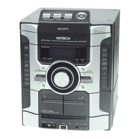
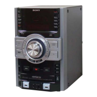
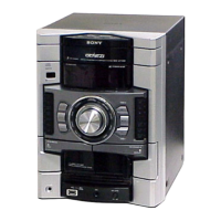
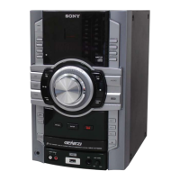
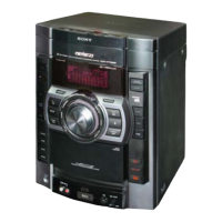
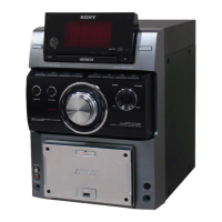
Overview of the unit's front and top controls and their functions.

Getting Started Guide

Initial setup guide for connecting components and setting the clock.

DISASSEMBLY

3-1. Disassembly Flow

Outlines the step-by-step procedure for disassembling the unit.

3-2. Side-L/R Case

Details the procedure for removing the side panels of the unit.

3-3. Top Panel Block

Explains how to remove the top panel assembly.

3-4. Tape Mechanism Deck

Provides instructions for removing the tape deck mechanism.

TEST MODE

PANEL TEST MODE

Checks LEDs, keys, model, destination, and software version.

COMMON TEST MODE

Tests amplifier and tape functions, including volume and GEQ levels.

COLD RESET Procedure

Clears all data, including EEPROM settings, to initial conditions.

VACS ON/OFF Function

Switches the Variable Attenuation Control System (VACS) on or off.

ELECTRICAL ADJUSTMENTS

DECK SECTION Adjustments

Adjusts record/playback head azimuth for optimal L-CH and R-CH output.

CD SECTION Checks

Checks CD block for adjustments, lens cleaning, and S-curve symmetry.

Tuner and RF Level Checks

Details FM tune level checks and RF signal level verification.

DIAGRAMS

7-1. Block Diagram - CD Servo, USB Section

Shows the block diagram for the CD servo and USB interface.

7-3. Block Diagram - AMP Section

Presents the block diagram for the amplifier section, including power stages.

7-5. Schematic Diagram - CD Board (1/2)

Part 1 of the CD board schematic diagram, detailing its circuitry.

EXPLODED VIEWS

8-1. Case Section

Shows an exploded view of the unit's outer case components and their assembly.

8-2. Loading Panel Section

Provides an exploded view of the loading panel assembly, including screws and parts.

8-3. Display Board Section

Shows an exploded view of the display board, including related components and part numbers.

ELECTRICAL PARTS LIST

9V REG BOARD Components

Lists electrical components for the 9V regulator board, including capacitors, ICs, and resistors.

CD BOARD Components

Lists components for the CD board, such as capacitors, connectors, diodes, ICs, transistors, and resistors.

SUPPLEMENT-1

1. New/Former Discrimination

Identifies differences between former and new versions of boards in the set.

2. Diagrams

Provides updated schematic diagrams and printed wiring boards for changed components.

3. Electrical Parts List

Lists electrical parts for the updated boards, including part numbers and descriptions.

REVISION HISTORY

Related product manuals