– 10 –
Tape Speed Adjustment DECK A DECK B
Procedure :
Mode : Playback
+
–
Output level measurement point
(see page 9)
set
frequency counte
test tape
WS-48B
(3kHz, – 0dB)
1. Set to FWD playback mode.
2. Adjust RV380 so that the frequency counter reading becomes 3,000
± 15Hz.
r Frequency difference between the begining and the end of the tape
should be within ± 3%.
r Frequency difference between deck A and deck B the bigining of
the tape should be within 1.5%.
Adjustment Location : MAIN board. (see page 11)
Playback Level Adjustment DECK A DECK B
Procedure :
Mode : Playback
set
Output level measurement point
(see page 9)
level meter
+
–
test tape
P-4-L300
(315Hz, 0dB)
Deck A is RV301 (L-CH) and RV401 (R-CH), deck B is RV302 (L-
CH) and RV402 (R-CH) so that adjustment within adjustment level
as follows.
Adjustment Level :
OUTPUT level : –7.2 to –8.2dB (– 301.5 to 338.3 mV)
level Difference between Channels : within 0.5dB
Comfrim the OUTPUT level does not change in playback mode while
changing the mode from playback to stop several times.
Adjustment Location : MAIN board. (see page 11)
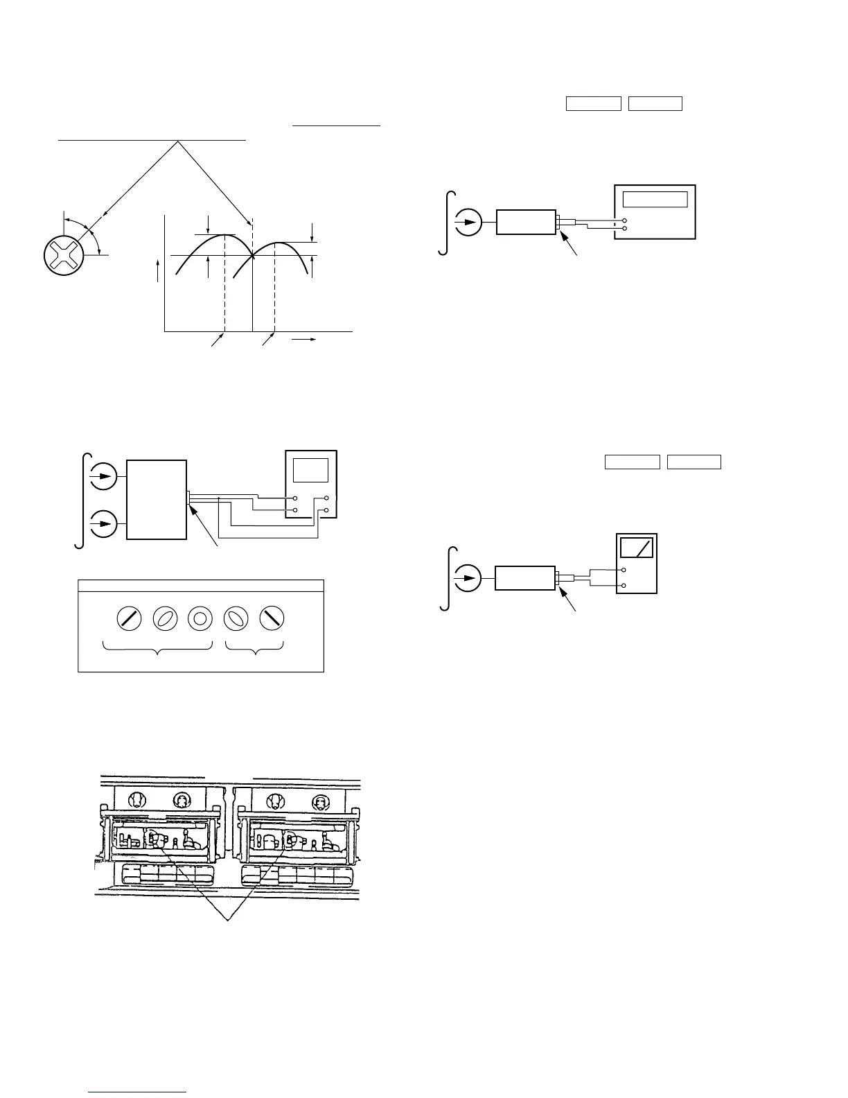
2. Turn the adjustment screw for the maximum output levels. If these
levels do not match, turn the adjustment screw until both of out-
put levels match together within 1dB.
L-CH
peak
R-CH
peak
L-CH
peak
R-CH
peak
Screw
position
output
level
within
1 dB
within
1 dB
screw position
3. Mode : Playback
V
H
in phase 45
°
90
°
135
°
180
°
good
wrong
set
screen pattern
L
L-CH
R-CH
R
test tape
P-4-A100
(10kHz, –10dB)
oscilloscope
Output level measurement point
(see page 9)
4. Change the review playback mode and repeat the steps 1 to 3.
5. After the adjustment, lock the adjustment screw with suitable lock-
ing compound.
Adjustment Location :
Adjustment screws
REC/PB head (deck B)
or PB head (deck A)