HCD-H331/H331D
MINI Hi-Fi COMPONENT SYSTEM
US Model
HCD-H331/H331D
Canadian Model
E Model
Australian Model
HCD-H331
r
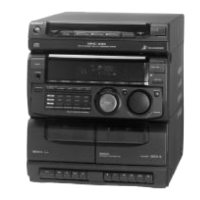
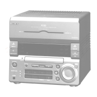
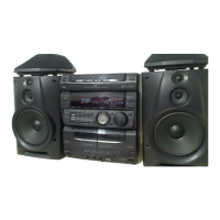
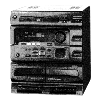
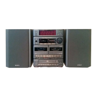
HCD-H331/H331D is the tuner, deck,
CD and amplifier section in MHC-331,
MHC-D2, MHC-G33.
Photo : HCD-H331
Dolby noise reduction manufactured under license from
Dolby Laboratories Licensing Corporation.
“DOLBY” and the double-D symbol a are trademarks of
Dolby Laboratories Licensing Corporation.
AUDIO POWER SPECIFICATIONS
POWER OUTPUT AND TOTAL
HARMONIC DISTORTION :
with 6 ohm loads, both channels driven,
from 40-20kHz ; rated 100 watts per
channel minimum RMS power, with no
more then 0.9 % total harmonic distortion
from 250 milliwatts to rated output.
CD player section
System Compact disc and digital audio
system
Laser Semiconductor laser
Laser output Max 44.6µW*
*This output is the value measured at
a distance of 200 mm from the ob-
jective lens surface on the Optical
Pick-up Block with 7 mm aperture.
Wavelength 780–790 nm
Frequency response
2Hz – 20kHz (± 0.5 dB)
Signal-to-noise ratio
More than 90 dB
Dynamic range
More than 90 dB
Tuner section
FM stereo, FM/AM superheterodyne tuner
FM tuner section
Tuning range US, Canadian model :
87.5 - 108MHz (100kHz step)
EXCEPT US, Canadian model :
87.5 - 108MHz (50kHz step)
Antenna FM lead antenna
Antenna terminals
75 ohm unbalanced
Intermediate frequency
10.7 MHz
AM tuner section
Tuning range
US, Canadian model :
531-1,710kHz (with the tuning
interval set at 9 kHz)
530-1,710kHz (with the tuning
interval set at 10 kHz)
E, Argentine, Australian, Mexican
model :
531-1,602kHz (with the tuning
interval set at 9 kHz)
530-1,710kHz (with the tuning
interval set at 10 kHz)
Antenna AM loop antenna
External antenna terminals
Intermediate frequency
450kHz
Amplifier section
US, Canadian model :
FTC 100W+100W (8ohm, 40-20kHz, 0.9% THD)
Continuous RMS power output
120W + 120W (8 ohm, 1kHz, 5% THD)
EXCEPT US, Canadian model :
Peak music power output
400W
Continuous RMS power output
20W + 20W (6 ohm, 1kHz, 10% THD)
Inputs
VIDEO IN (phono jacks) :
voltage 450 mV
impedance 47 kilohm
Outputs
PHONES (stereo phono jack) :
accepts headphones of 8 ohm or more
SPEAKER :
accepts impedance of 6 to 16 ohm
SUPER WOOFER :
voltage 1V, impedance 1 kilohms
(HCD-H331 only)
–Continued on page 2–
SPECIFICATIONS
CD
Section
Model Name Using Similar Mechanism HCD-H881/H881D
CD Mechanism Type CDM38-5BD19
Base Unit Name BU-5BD19
Tape deck
Section
Model Name Using Similar Mechanism NEW
Tape Transport Mechanism Type TCM-YSW47C24
SERVICE MANUAL
MICROFILM