– 9 –
SECTION 4
MECHANICAL ADJUSTMENTS
SECTION 5
ELECTRICAL ADJUSTMENTS
PRECAUTION
1. Clean the following parts with a denatured-alcohol-moistened
swab :
record/playback head pinch rollers
erase head rubber belts
capstan
2. Demagnetize the record/playback head with a head demagnetizer.
3. Do not use a magnetized screwdriver for the adjustments.
4. After the adjustments, apply suitable locking compound to the
parts adjusted.
5. The adjustments should be performed with the rated power sup-
ply voltage unless otherwise noted.
rTorque Measurement
Mode Torque meter Meter reading
FWD CQ-102C
30 to 80 g • cm
(0.42–1.11 oz• inch)
FWD
CQ-102C
1.5 to 5.5 g • cm
Back Tension
(0.021–0.076 oz• inch)
FF/REW CQ-201B
55 to 130 g • cm
(0.77–1.80 oz• inch)
rTape Tension Measurement
Torque Meter Meter Reading
CQ-403A
more than 100g
(more than 3.53 oz)
DECK SECTION
1. The adjustment should be performed in the publication.
(Be sure to make playback adjustment at first.)
2. The adjustment and measurement should be performed for both
L-CH and R-CH.
r Switch position
DOLBY NR switch : OFF
FUNCTION button : OFF
EFECT switch : OFF
DBFB switch : OFF
3. Input point and output level measurement point.
r
Tast tape
Tape Contents Use
P-4-A100 10kHz, –10dB Head Azimuth Adjustment
P-4-L300 315Hz, 0dB Level Adjustment
WS-48B 3kHz, 0dB Tape Speed Adjustment
0db=0.775V
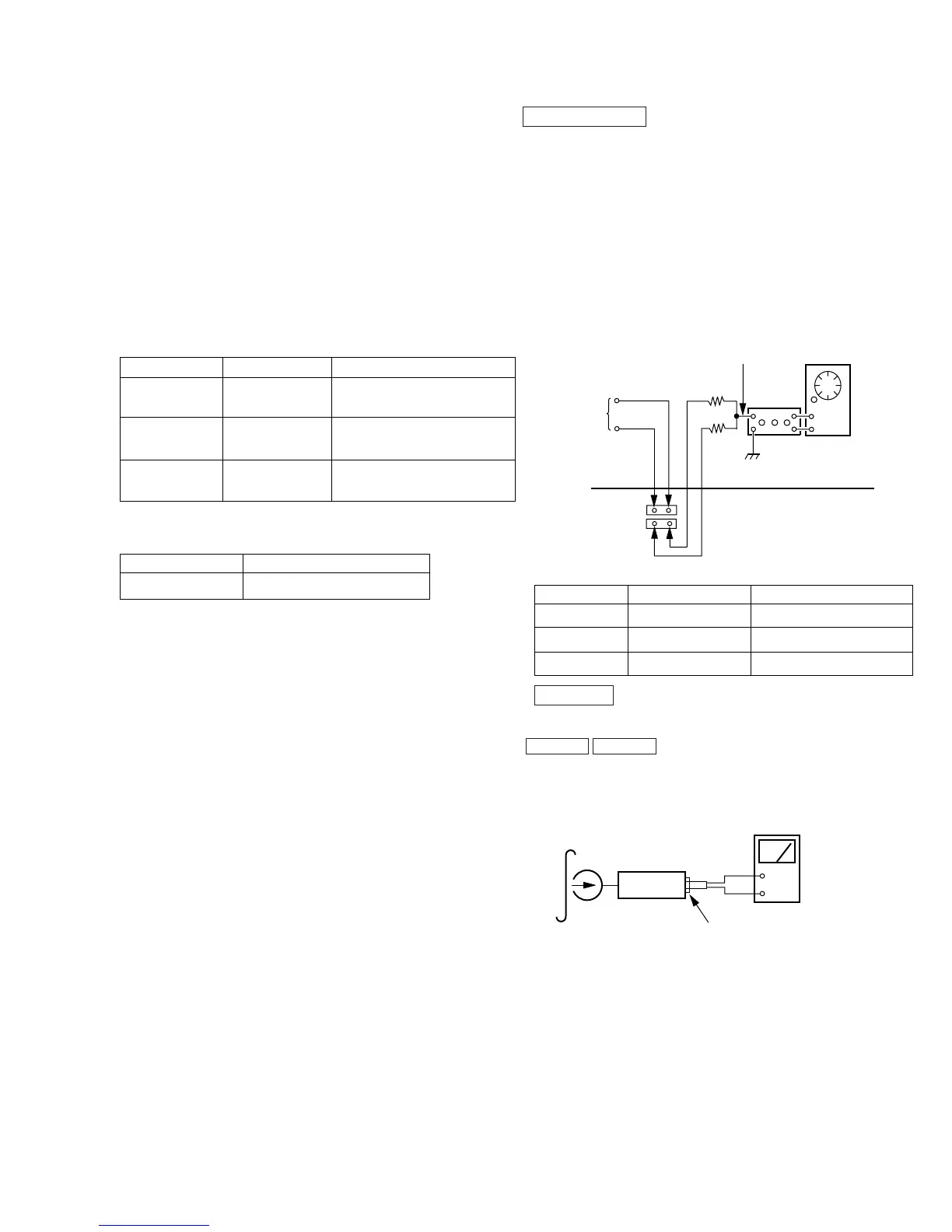
Record/Playback Head Azimuth Adjustment
DECK A DECK B
Procedure :
1. Mode : Playback
set
Output level measurement point
level meter
+
–
test tape
P-4-A100
(10kHz, – 10dB)
AF OSC
attenuator
47k
Ω
47k
Ω
51.2mV (–23.6dB)
CN307
R-CH
L-CH
CN308
MAIN BOARD
(Component side)
– Input point –
Output level
– measurement –
point
3
3
1
1
Output level
measurement
point