– 2 –
TABLE OF CONTENTS
1. SERVICING NOTES
................................................. 3
2. GENERAL
Index to Parts and Controls ............................................... 5
3. DISASSEMBLY............................................................ 7
4. MECHANICAL ADJUSTMENTS ......................... 11
5. ELECTRICAL ADJUSTMENTS
Deck Section...................................................................... 11
Tuner Section ..................................................................... 14
CD Section......................................................................... 15
6. DIAGRAMS
6-1. IC Pin Function Description .............................................. 17
6-2. Block Diagrams
CD Section......................................................................... 21
Main Section...................................................................... 23
6-3. Schematic Diagram – Main Section – ............................... 28
6-4. Printed Wiring Boards – Main Section – ........................... 33
6-5. Schematic Diagram – Tuner Section –
(AEP, G, IT, UK model) .................................................... 38
6-6. Printed Wiring Board –Tuner Section –
(AEP, G, IT, UK model) .................................................... 40
6-7. Printed Wiring Board –Tuner Section –
(EXCEPT AEP, G, IT, UK model) .................................... 41
6-8. Schematic Diagram – Tuner Section –
(EXCEPT AEP, G, IT, UK model) .................................... 42
6-9. Schematic Diagram – CD Section – .................................. 44
6-10. Printed Wiring Board –CD Section – ................................ 47
6-11. Schematic Diagram – Deck Section – ............................... 51
6-12. Printed Wiring Boards –Deck Section –............................ 53
6-13. Printed Wiring Board – Power Section –........................... 56
6-14. Schematic Diagram – Power Section – ............................. 57
6-15. Schematic Diagram – Panel Section –............................... 61
6-16. Printed Wiring Boards – Panel Section – .......................... 63
7. EXPLODED VIEWS .................................................. 65
8. ELECTRICAL PARTS LIST.................................. 72
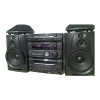
DIN power output:
Satellite 7 W+7 W (4 ohms at 1 kHz, DIN)
Superwoofer 30 W (6 ohms at 60 Hz, DIN)
Continuous RMS power output
Satellite 10 W+10 W (4 ohms at 1 kHz, 10% THD)
Superwoofer 35 W (6 ohms at 60 Hz, 10%THD)
Music power output
Satellite 15 W+15 W (4 ohms at 1 kHz, 10% THD)
Supperwoofer 45 W (6 ohms at 60 Hz, 10% THD)
Inputs
MD IN Sensitivity 450 mV, impedance 47 kilohms
Output
MD OUT Sensitivity 250 mV, 1 kilohms
PHONES (stereo phone jack)
accept headphones of 8 ohms or more.
General
• Abbreviation
G : German
IT : Italian
Destination Power requirements
Power
consumption
Dimensions Approx. 225 × 210 × 235 mm
(w/h/d) incl. projecting
parts and controls
Mass Approx. 4.8 kg
Design and specifications are subject to change without notice.
AEP, UK, German,
220-230 V AC, 50/60 Hz
Italian model
E, Saudi Arabia,
Hong Kong,
110-120 V/220-240 V AC,
75 W
Singapore, Argentine,
50/60 Hz Adjustable with
Malaysia model
the voltage selector
Mexican model 120 V AC, 60 Hz
Australian model 240 V AC, 50/60 Hz
w
w
w
.
x
i
a
o
y
u
1
6
3
.
c
o
m
Q
Q
3
7
6
3
1
5
1
5
0
9
9
2
8
9
4
2
9
8
T
E
L
1
3
9
4
2
2
9
6
5
1
3
9
9
2
8
9
4
2
9
8
0
5
1
5
1
3
6
7
3
Q
Q
TEL 13942296513 QQ 376315150 892498299
TEL 13942296513 QQ 376315150 892498299
http://www.xiaoyu163.com
http://www.xiaoyu163.com