77
HCD-HDX265/HDX266/HDX267W/HDX465/HDX466/HDX665
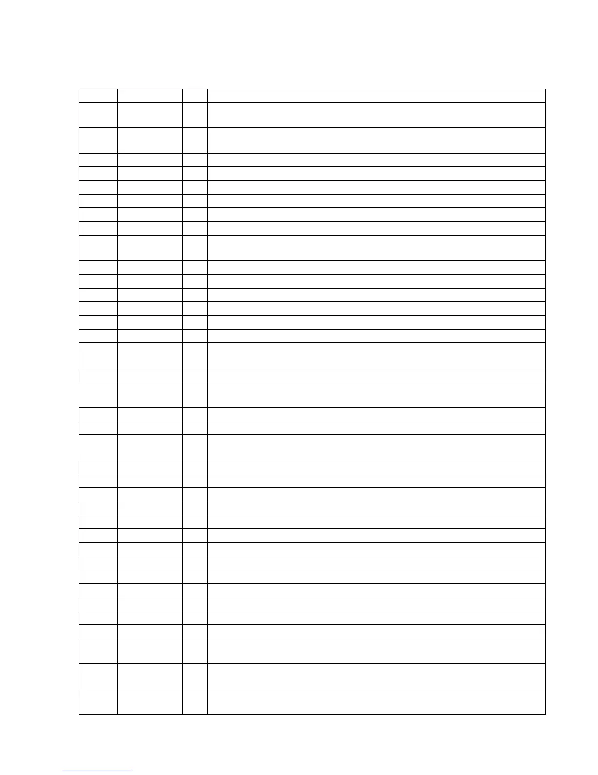
• IC Pin Function Description
MAIN BOARD IC501 M30622MGP-A58FPU0 (SYSTEM CONTROLLER)
Pin No. Pin Name I/O Description
1
Serial data output to the stream processor, DIR-TC1 slot
Serial data transfer clock signal output to the stream processor, DIR-TC1 slot
3 CEC_RX_IN I CEC serial data input from the HDMI OUT connector
4 SIRCS_IN I SIRCS signal input from the remote control receiver
5 to 7
BYTE
I
External data bus width selection signal input terminal Fixed at "L" in this set
I Processor mode switch input terminal (for test) Fixed at "L" in this set
EN_A, EN_B I Jog dial pulse input from the rotary encoder (for VOLUME)
System reset signal input from the reset signal generator "L": reset
For several hundreds msec. after the power supply rises, "L" is input, then it change to "H"
13 XOUT O Main system clock output terminal (5 MHz)
14 VSS - Ground terminal
15 XIN I Main system clock input terminal (5 MHz)
16 VCC - Power supply terminal (+3.3V)
17 NMI I Non-maskable interrupt input terminal Fixed at "H" in this set
18
I Output level detect terminal for the auto calibration
20
AC_CUT
I
AC cut detection signal input terminal "L": AC cut on
Serial data transfer clock signal output to the LED driver and fluorescent indicator tube driver
22 CEC_TX_OUT O CEC serial data output to the HDMI OUT connector
23 DIAT_CSOD
I Captor start delay signal input from the DIR-TC1 slot
O Serial data output to the LED driver and fluorescent indicator tube driver
25 NO USE O Not used
26 MIC_GAIN O
MIC gain control signal output terminal
27 CDM_OPEN_SW I Disc insert (8/12cm) detect switch input terminal "L": disc insert
28
DC_CONT
O
Muting on/off control signal output terminal
Serial data input from the DMPORT connector
Serial data output to the DMPORT connector
31 DVD_SID O Serial data output to the servo DSP
32 DVD_SOD I Serial data input from the servo DSP
33 DVD_SCO I Serial data transfer clock signal input from the servo DSP
34 DVD_XIFBUSY O Busy signal output to the servo DSP
35, 36 NO USE O Not used
37 DVD XIFCS I Chip select signal input from the servo DSP
38 MTK RST O
Reset signal output to the servo DSP and flash memory "L": reset
O Power on/off control signal output terminal "H": power on
42
Reset signal output to the digital power amplifier "L": reset
Shut down state input from the digital power amplifier "L": shut down


 To Next Page