HCD-PZ1D
5
VIDEO SIGNAL CONFIRMATION METHOD
This unit can display the video of the connected cyber shot on the
LCD module.
Execute the method of the following when the defective video sig-
nal unit is brought in, and judge whether the main unit or Party-
shot & cyber shot is defective.
Procedure:
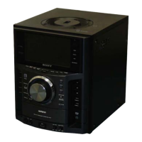
1. Prepare the jig (Part No. 1-771-264-11).
pin 3
(VIDEO GND)
Note:
Connect pin 2 between
pin 3 with the lead wire.
pin 2
(GND)
pin 4
(VIDEO SIGNAL)
pin 1
(POWER SUPPLY)
+4.2 V ± 0.15 V
jig
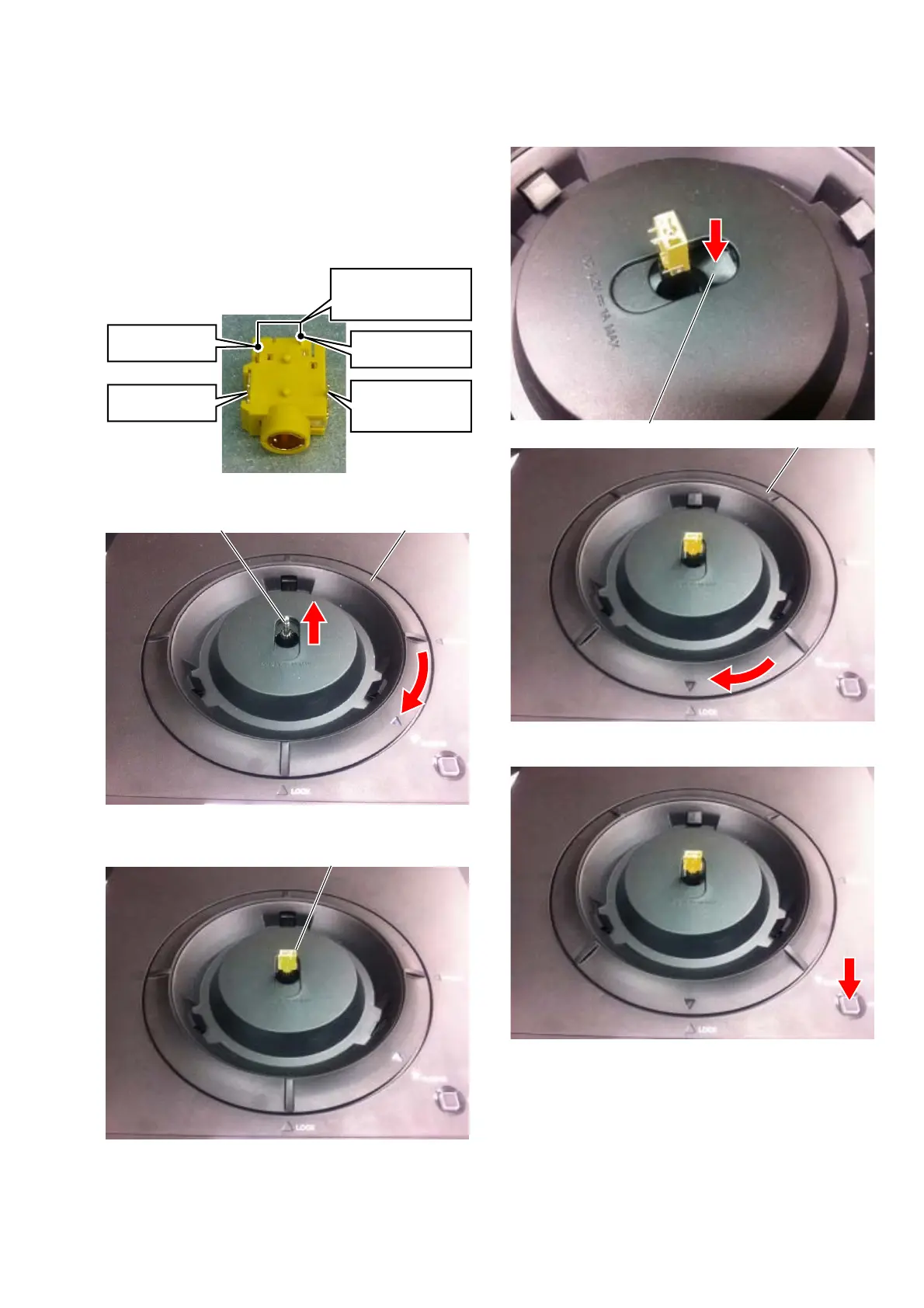
2. Turn LOCK RING in the direction of [PLUG IN].
LOCK RINGPOWER PLUG
3. Attach the jig with the POWER PLUG.
JIG
4. Keep pushing the SHUTTER (A) on, and turn LOCK RING in
the direction of [LOCK].
SHUTTER (A)
LOCK RING
5. Press the [Party-shot SYNC] button.
6. Confi rm the voltage between pin 1 (POWER SUPPLY) and
pin 2 (GND) of jig is a standard value.
Standard value:
[Party-shot SYNC] indicator lighting : +4.2 V ± 0.15 V
[Party-shot SYNC] indicator blinking : +4.8 V ± 0.15 V
When [Party-shot SYNC] indicator is turned off : 0 V
7. Input the video signal (composite video out signal from DVD
player etc.) between pin 3 (VIDEO GND) and pin 4 (VID-
EO SIGNAL), and confi rm the video is displayed on the LCD
module.
 Loading...