EasyManua.ls Logo

Sony HCD-RG70AV User Manual

Sony HCD-RG70AV
76 pages
To Next Page IconTo Next Page
Page #1 background imageLoading...
Page #1 background image
SERVICE MANUAL
MINI HI-FI COMPONENT SYSTEM
US Model
AEP Model
HCD-RG70AV
E Model
HCD-DX60AV
SPECIFICATIONS
HCD-DX60AV/RG70AV
Ver 1.2 2003.07
9-873-839-13 Sony Corporation
2003G05-1 Home Audio Company
C 2003.07 Published by Sony Engineering Corporation
HCD-DX60AV/RG70AV is the tuner,
deck, CD and amplifier section in MHC-
DX60AV/RG70AV.
Dolby noise reduction manufactured under license
from Dolby Laboratories Licensing Corporation.
“DOLBY” and the double-D symbol ; are trade-
marks of Dolby Laboratories Licensing Corporation.
Model Name Using Similar Mechanism HCD-DX90
CD
CD Mechanism Type CDM58B-K6BD38
Section
Base Unit Name BU-K6BD38
Optical Pick-up Block Name KSM-213DCP
Optical Pick-up Name KSS-213D
Tape deck
Model Name Using Similar Mechanism NEW
Section
Tape Transport Mechanism Type CWL44RR-31
– Continued on next page –
Photo: HCD-RG70AV
AUDIO POWER SPECIFICATIONS:
(HCD-RG70AV US model only)
POWER OUTPUT AND TOTAL
HARMONIC DISTORTION:
with 6 ohm loads both channels driven, from
120 – 10,000 Hz; rates 60 watts per channel
minimum RMS power, with no more than 10%
total harmonic distortion from 250 milliwatts to
rated output.
Amplifier section
North American model:
HCD-RG70AV
Front speaker:
Continuous RMS power output (reference)
60 + 60 watts
(6 ohms at 1 kHz,
10% THD)
Total harmonic distortion less than 0.07%
(6 ohms at 1 kHz,
30 watts)
Center speaker:
Continuous RMS power output (reference)
40 watts
(6 ohms at 1 kHz,
10% THD)
Rear speaker:
Continuous RMS power output (reference)
40 + 40 watts
(6 ohms at 1 kHz,
10% THD)
European model:
HCD-RG70AV
Front speaker:
DIN power output (rated) 40 + 40 watts
(6 ohms at 1 kHz, DIN)
Continuous RMS power output (reference)
50 + 50 watts (6 ohms at
1 kHz, 10% THD)
Music power output (reference)
95 + 95 watts (6 ohms at 1
kHz, 10% THD)
Center speaker:
DIN power output (rated) 25 watts
(6 ohms at 1 kHz, DIN)
Continuous RMS power output (reference)
35 watts (6 ohms at 1 kHz,
10% THD)
Music power output (reference)
65 watts (6 ohms at 1 kHz,
10% THD)
Rear speaker:
DIN power output (rated) 25 + 25 watts
(6 ohms at 1 kHz, DIN)
Continuous RMS power output (reference)
35 + 35 watts (6 ohms at
1 kHz, 10% THD)
Music power output (reference)
65 + 65 watts (6 ohms at 1
kHz, 10% THD)

Table of Contents

Question and Answer IconNeed help?

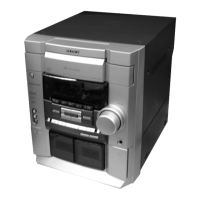
Do you have a question about the Sony HCD-RG70AV and is the answer not in the manual?

Sony HCD-RG70AV Specifications

General IconGeneral
TypeStereo System
CD PlayerYes
TunerAM/FM
Cassette DeckYes
Remote ControlYes
Audio Channels2.0
Surround SoundNo
Power Output100 Watts

Summary

SPECIFICATIONS

AUDIO POWER SPECIFICATIONS

Detailed power output and harmonic distortion specifications for audio sections.

POWER OUTPUT AND TOTAL HARMONIC DISTORTION

Specifies power output and distortion levels for amplifier sections.

NOTES ON HANDLING THE OPTICAL PICK-UP BLOCK OR BASE UNIT

NOTES ON LASER DIODE EMISSION CHECK

Precautions for checking laser diode emission, emphasizing safe distance.

SAFETY CHECK-OUT

LEAKAGE TEST

Procedure for testing AC leakage from exposed metal parts to ground.

SECTION 2 DISASSEMBLY

Disassembly Flow

Provides a step-by-step flow chart for disassembling the unit.

Case (Top)

Details the procedure for removing the top case.

CD Door

Explains how to remove the CD door.

CD Mechanism Deck (CDM58B-K6BD38)

Procedure for removing the CD mechanism deck.

Tape Mechanism Deck

Procedure for removing the tape mechanism deck.

Back Panel Section

Details the disassembly of the back panel section.

SECTION 3 TEST MODE

MC Cold Reset

Resets system data to initial conditions, used before customer return.

CD Ship Mode

Positions the pickup for vibration durability, used for customer return.

SECTION 4 ELECTRICAL ADJUSTMENTS

Deck Section

Covers adjustments for tape deck heads and speed.

Tuner Section

Details FM tuned level and null adjustments.

CD Section

Covers S-curve, RF level, E-F balance, and RF PLL checks.

SECTION 6 EXPLODED VIEWS

Front Panel Section

Provides an exploded view of the front panel assembly.

Related product manuals