10
HCD-RV2/RV5/RV6
VIDEO SECTION
VIDEO LEVEL ADJUSTMENT
(AUDIO LEVEL/VIDEO CLOCK/AUDIO SERVO
CLOCK CHECK)
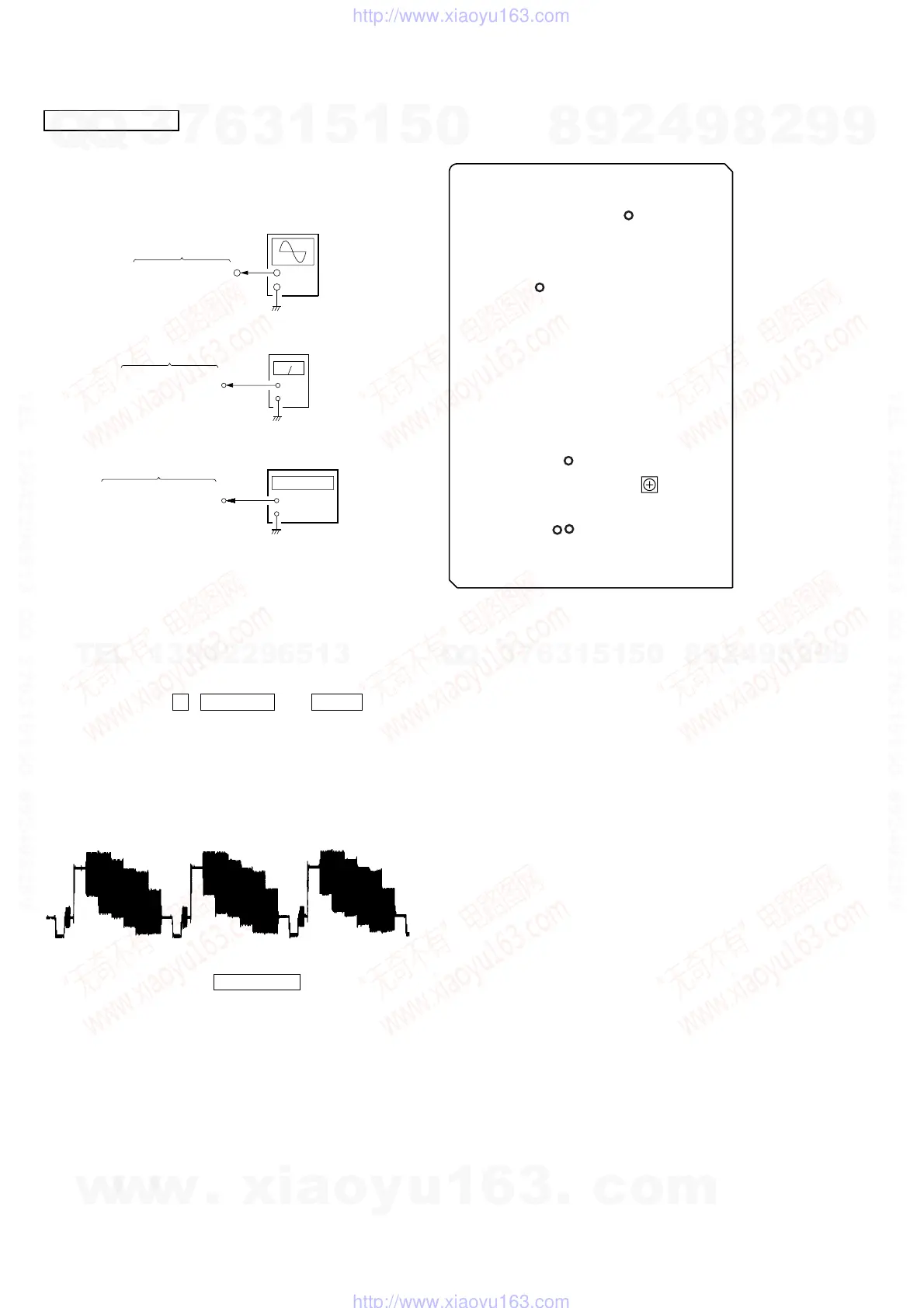
Procedure :
1. Connect an oscilloscope to TP308 (V-OUT) on the VIDEO board.
2. Connect a level meter to TP415 (L-OUT) and TP413 (R-OUT)
on the VIDEO board.
3. Connect a frequency counter to TP70 (54 MHz) and TP182
(4.2336 MHz) on the VIDEO board.
3. Turn the power ON.
4. Set a test disc (HLV-402 (Part No. 8-909-870-00))
5. Press three buttons x , MUSIC EQ , and DISC 3 simulta-
neously.
6. The message “MPEG AV TEST” is displayed on the fluorescent
indicator tube. Color bar signal outputs and sine-wave (1 kHz
0 dB) appears.
7. Adjust the RV501 on the VIDEO board for 0.714 ± 0.05 Vp-p.
Note: TP308 (V-OUT) on the VIDEO board must be teminated by
75 Ω.
8. Confirm that the value of level meter is 2.5 ± 2.0 dBs. (If audio
output disappear, press the PLAY MODE button twice)
9. Confirm that the value of frequency counter is 54 MHz ± 400
Hz.
10.Confirm that the value of frequency counter is 4,2336 MHz.
11.Change disc to a MP3 test disc (MP3 1kHz 0dB sine-wave is
recorded)
12.Confirm that the value of level meter is 2.4 ± 2.0 dBs.
Connecting and Adjustment Location:
VIDEO board
TP308 (V-OUT)
+
–
oscilloscope
+
–
level meter
VIDEO board
TP415 (L-OUT)
TP413 (R-OUT)
VIDEO board
TP70 (54 MHz)
TP182 (4.2336 MHz)
+
–
frequency counte
– VIDEO BOARD (Component Side) –
TP308
(V-OUT)
TP70
(54 MHz)
TP182
(4.2336 MHz)
TP415
(L-OUT)
TP413
(R-OUT)
RV501
Video
Level
Adjustment
w
w
w
.
x
i
a
o
y
u
1
6
3
.
c
o
m
Q
Q
3
7
6
3
1
5
1
5
0
9
9
2
8
9
4
2
9
8
T
E
L
1
3
9
4
2
2
9
6
5
1
3
9
9
2
8
9
4
2
9
8
0
5
1
5
1
3
6
7
3
Q
Q
TEL 13942296513 QQ 376315150 892498299
TEL 13942296513 QQ 376315150 892498299
http://www.xiaoyu163.com
http://www.xiaoyu163.com