Do you have a question about the Sony HCD-S888 and is the answer not in the manual?
Detailed specifications for the amplifier section, including stereo and surround modes.
Technical details of the FM tuner, covering tuning range and intermediate frequency.
Technical details of the AM tuner, including tuning range and intermediate frequency.
Specifications related to the Super Audio CD and DVD playback system, including laser details.
Technical specifications for video inputs and outputs, including voltage and impedance.
Explains display codes for system malfunctions and troubleshooting steps.
Precautions for handling the optical pick-up due to static sensitivity and board fragility.
Safety guidelines for checking the laser diode emission, specifying observation distance.
Overview of the test mode, its purpose, and usage with a monitor.
Lists the required test discs for specific diagnostic and adjustment procedures.
Step-by-step instructions on how to enter the system's test mode.
Details on how to navigate and use the test mode menus and functions.
Procedure for automatically adjusting servo circuits for discs.
High-level functional block diagrams illustrating system architecture.
Block diagram detailing the RF servo signal path and components.
Block diagram showing the digital signal processing for audio.
Block diagram illustrating audio output and front panel connections.
Block diagram detailing the video signal flow and processing.
Block diagram of the mechanism deck and power supply units.
Explains conventions used in schematic diagrams and printed wiring boards.
| Type | DVD Player |
|---|---|
| Brand | Sony |
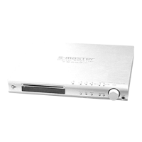
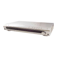
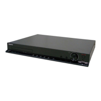
| Model | HCD-S888 |
| Category | DVD Player |
| Playable Media | DVD, CD |
| Speakers | Yes |
| Disc Capacity | 1 |
| Tuner Bands | FM |
| Output Power | 100W |
| Surround Sound | Dolby Digital |
| Supported Disc Types | DVD, CD |