Do you have a question about the Sony HCD-DZ500F and is the answer not in the manual?
Details of the amplifier's stereo and surround mode power outputs.
Technical specifications for the CD/DVD playback system, including laser type.
Explanation of the self-diagnosis function and how to interpret service numbers.
A flowchart outlining the step-by-step disassembly procedure of the unit.
Procedure for removing the DVD mechanism deck assembly.
Detailed steps and diagram for disassembling the case and front panel assembly.
Procedure to reset all stored data to initial conditions when returning the set to the customer.
Modes to check software version, LCD, LED, and keyboard functionality.
Mode used after repair to prepare the set for shipping, involving a "MECHA LOCK" display.
Procedure to enter the Remocon Diagnosis Menu for system testing and adjustments.
Menu for manually controlling drive functions like servo, track jump, and tray aging.
Command to check the mirror time value specifically for CD discs.
Step in the adjustment procedure to select the MIRR time Adjust option.
Command to check the mirror time value specifically for DVD discs.
Step to select the default mirror time setting function.
Initial step to enter the diagnosis menu by pressing specific buttons.
Step to navigate to the Drive Manual Operation menu.
Step to select the manual adjustment sub-menu from Drive Manual Operation.
Step to select the IOP measurement function from the manual adjustment list.
Block diagram and pin functions for the CXD9775M integrated circuits.
Block diagrams and pin functions for the CXD9843AR stream processor ICs.
Detailed block diagram and pinout for the FL driver IC.
Comprehensive list of pin names, I/O, and descriptions for the system controller IC.
Detailed pinout information for the system controller IC, covering pins 46-92.
Description of the multiple functions integrated into IC102.
Exploded view of the entire unit, showing the main assemblies and their relationships.
Continuation of the MAIN board resistors list.
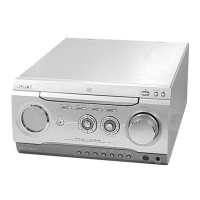
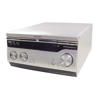
| Type | DVD Player |
|---|---|
| Model | HCD-DZ500F |
| Brand | Sony |
| Number of Discs | 1 |
| Playable Media Format | DVD, CD, MP3 |
| Surround Sound | Dolby Digital, DTS |
| Output Power | 1000W |
| Speakers | 5.1 Channel |
| USB Port | Yes |
| HDMI Output | Yes |
| Tuner Bands | FM |
| Playback Formats | DVD, CD, MP3 |