EasyManuals Logo

Sony HT-RT40 Service Manual

Sony HT-RT40
38 pages
To Next Page IconTo Next Page
To Previous Page IconTo Previous Page
Page #11 background imageLoading...
Page #11 background image
HT-RT4/RT40
11
2-4. LOUDSPEAKER 16CM
– Front view –
1 six screws ((1) (4 x 20), +BV TAPPING)
5 CN1001 (4P)
2 Remove the loudspeaker 16cm
in the direction of the arrow.
4 loudspeaker 16cm
3 terminal
(narrow side)
3 terminal
(wide side)
loudspeaker 16cm
loudspeaker 16cm
terminal position
,QVWDOODWLRQGLUHFWLRQIRUWKHORXGVSHDNHU
FP
terminal (wide side)
:LUHVHWWLQJ
front side
terminal (narrow side)
Note:
When you install the connector, please install them correctly.
There is a possibility that this machine damages when not
correctly installing it.
Insert is shallow
Insert is straight
to the interior.
connector
Insert is incline
connector
connector
connector
connector connector
OK NG NG

Other manuals for Sony HT-RT40

Questions and Answers:

Question and Answer IconNeed help?

Do you have a question about the Sony HT-RT40 and is the answer not in the manual?
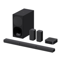
Sony HT-RT40 Specifications

General IconGeneral
Total Power Output600W
Speaker Configuration5.1 channel
HDMI Output1 (ARC)
Sound ModesMusic, Cinema, Standard
ConnectivityBluetooth, USB
SubwooferWired
Surround SoundDolby Digital
Input and Output TerminalsOptical Input, Analog Input, USB

Related product manuals