34
HT-RT4/RT40
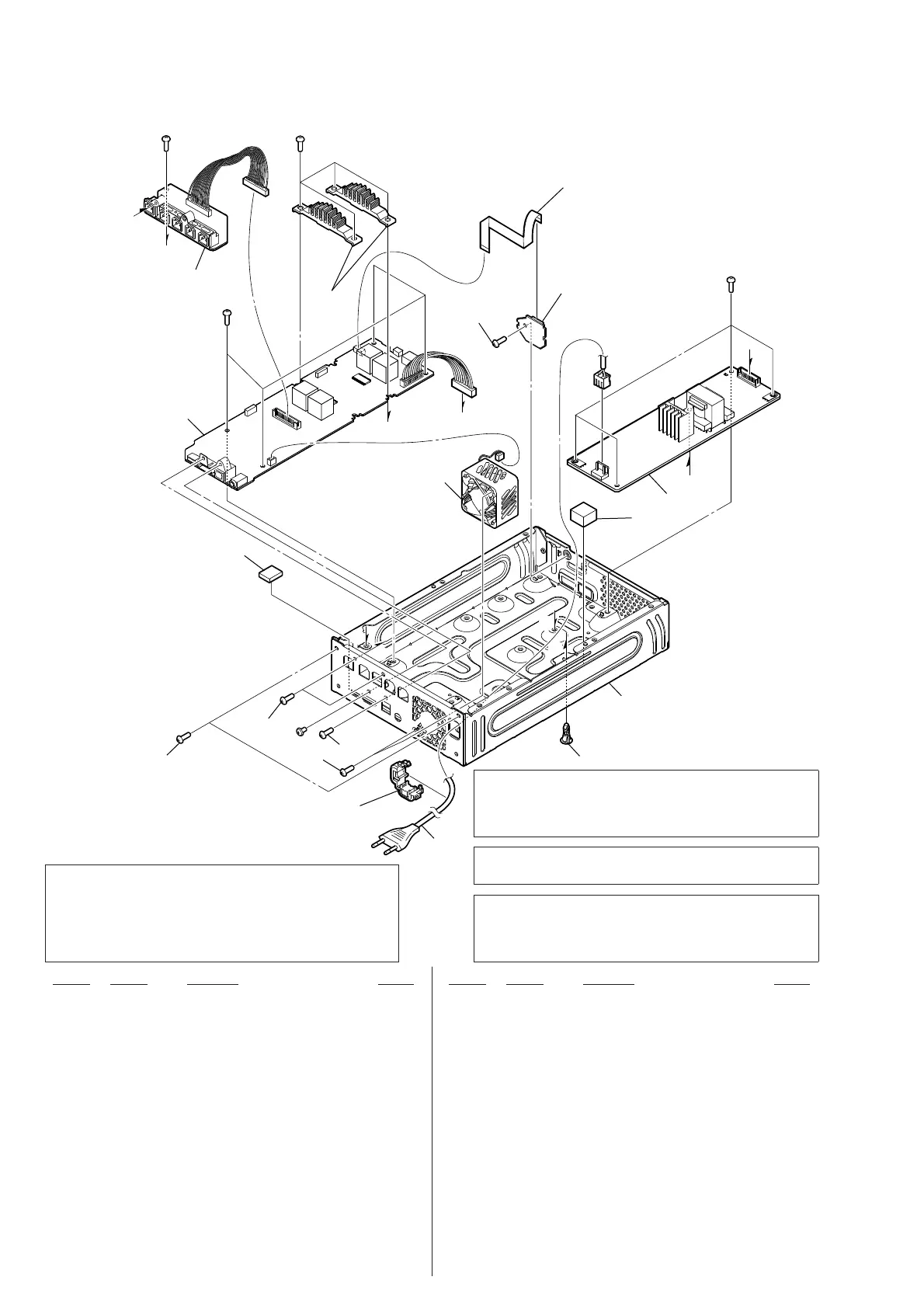
6-3. MAIN BOARD SECTION
Ref. No. Part No. Description Remark Ref. No. Part No. Description Remark
101 3-077-331-41 +BV3 (3-CR)
0 102 1-855-244-11 DC FAN
9 103 A-2180-047-A MAIN BOARD, COMPLETE (for SERVICE)
(RT4: AEP)
9 103 A-2180-095-A MAIN BOARD, COMPLETE (for SERVICE)
(RT4: UK)
9 103 A-2180-101-A EG4 MAIN BOARD, COMPLETE (for SERVICE)
(RT40: E12)
9 103 A-2180-118-A EG4 MAIN BOARD, COMPLETE (for SERVICE)
(RT40: AUS)
9 103 A-2180-203-A EG4 MAIN BOARD, COMPLETE (for SERVICE)
(RT40: SP)
9 103 A-2180-265-A EG4 MAIN BOARD, COMPLETE (for SERVICE)
(RT40: LA9)
9 103 A-2180-281-A EG4 MAIN BOARD, COMPLETE (for SERVICE)
(RT40: AR)
9 103 A-2180-482-A EG4 MAIN BOARD, COMPLETE (for SERVICE)
(RT40: EA)
9 103 A-2180-494-A EG4 MAIN BOARD, COMPLETE (for SERVICE)
(RT40: E3)
104 1-828-228-51 WIRE (FLAT TYPE) (20 CORE)
0 105 4-966-267-12 BUSHING (FBS001), CORD
0 106 1-834-966-42 POWER-SUPPLY CORD (AEP, E3, SP, LA9)
0 106 1-835-068-21 CORD, POWER (AUS)
0 106 1-837-312-11 CORD, POWER-SUPPLY (AR)
0 106 1-839-999-22 POWER-SUPPLY CORD (UK, EA)
0 106 1-848-053-12 POWER-SUPPLY CORD (E12)
0 107 1-474-638-31 REGULATOR, SWITCHING 3L405W-4
(EXCEPT E12)
0 107 1-474-638-41 REGULATOR, SWITCHING 3L405W-5 (E12)
#1 7-685-646-71 SCREW +BVTP 3X8 TYPE2 IT-3
#3 7-682-546-09 SCREW +B 3X5
ns not supplied
Note 3: If wire (fl at type) is replaced, install it after bending
it in the same form as that before replacement.
Note 1: When the complete MAIN board (RT4) or EG4 MAIN
board (RT40) is replaced, refer to “NOTE OF RE-
PLACING THE IC1000 AND IC1002 ON THE MAIN
BOARD (RT4) OR EG4 MAIN BOARD (RT40) AND
THE COMPLETE MAIN BOARD (RT4) OR COM-
PLETE EG4 MAIN BOARD (RT40)” on page 5.
Note 2: When the REGULATOR, SWITCHING 3L405W
board is replaced, spread the bond referring to
“BOND FIXATION OF ELECTRIC PARTS” on
page 6.
Note 4: When the complete MAIN board (RT4) or EG4
MAIN board (RT40) is replaced, spread the bond
referring to“BOND FIXATION OF ELECTRIC
PARTS” on page 6.
A
B
C
C
D
D
B
E
E
A
#1
#1
#1
#3
#1
103
ns
102
105
104
101
101
101
101
101
107
106
ns
SPEAKER CHUKEI PC
BOAR board (ns)
ns
ns
ns
CONNECTOR board (ns)
 Loading...