HT-RT4/RT40
9
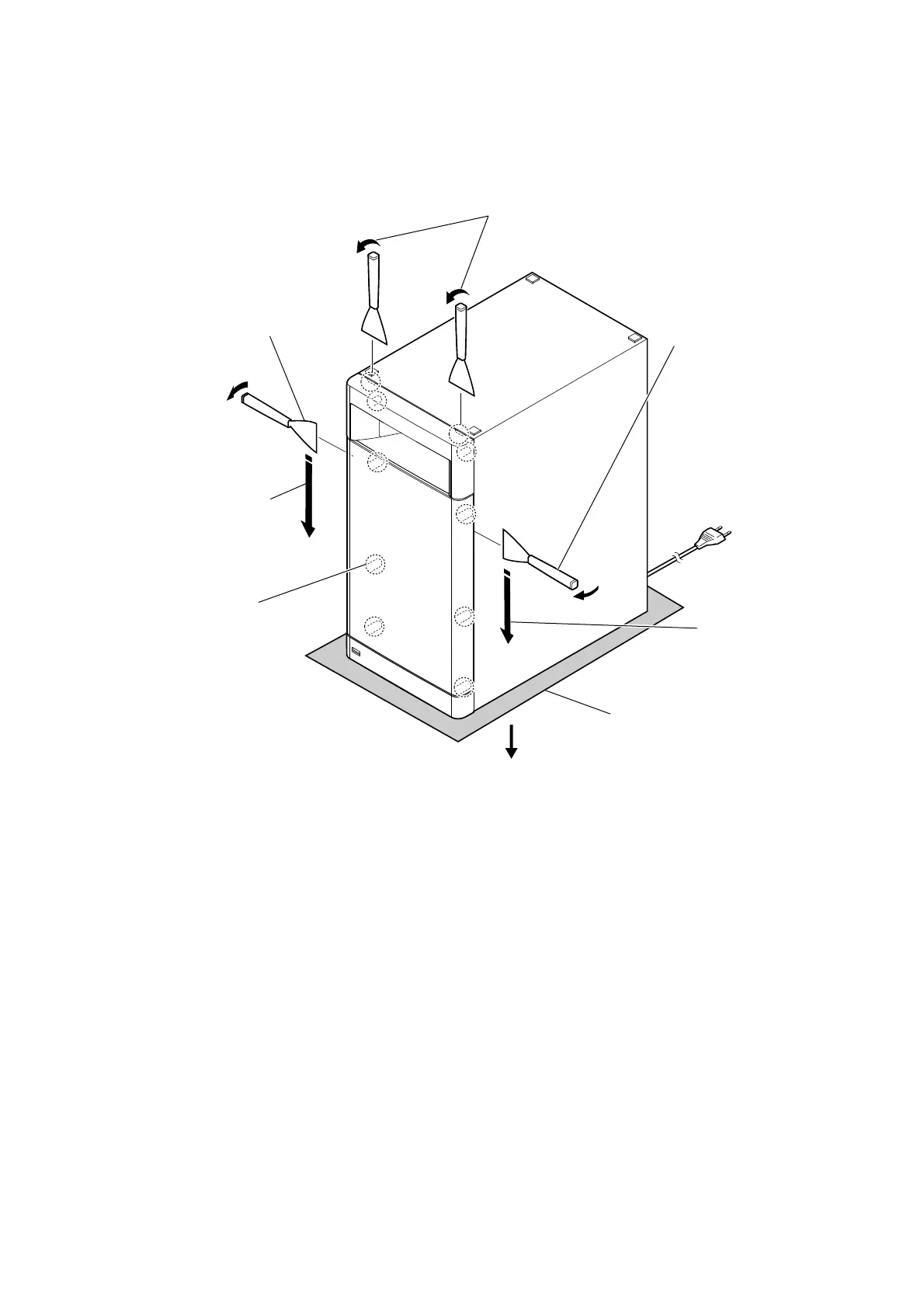
Note: Follow the disassembly procedure in the numerical order given.
2-2. FRONT PANEL SECTION-1
• Continued on next page.
total eight bosses
1 Insert a jig in two notches of
bottom of the unit, and lift the
front panel section a little.
3 All bosses are removed
while moving jig in the
direction of the arrow,
and front panel section
is removed.
3 All bosses are removed
while moving jig in the
direction of the arrow,
and front panel section
is removed.
Please spread a sheet
under a unit not to
injure cabinet.
2 Insert the jig into a space and
raise front panel section.
Note 2: When using a jig,
please work so as not
to injure front panel
section and cabinet.
2 Insert the jig into a space and
raise front panel section.
Note 2: When using a jig,
please work so as
not to injure front panel
section and cabinet.
Note 1:
– Bottom view –
top side
 Loading...