15
Back Up Battery Power
The back up battery located on the rear panel PK board powers the timer
Clock IC405 to keep the clock alive for about six months if no power is
applied. This battery is recharged whenever either power source is con-
nected because of the OR configured D401 and D402 diodes on the FC-
72 board.
Camera Stage
The camera stage consists of the lens assembly, CCD imager, and cir-
cuitry on the main FU-72 board. The main board circuits process the
signal for the LCD panel and for storage on the floppy disc. Additional
circuits control the iris, focus and zoom motors (not shown) in the lens
assembly.
At power ON, but only in the Still or Movie modes when the camera is
used, is when the iris motor opens to pass light through the lens onto the
CCD imager. The imager consists of thousands of phototransistors that
translate each pixel of incoming light into a voltage. With the aid of hori-
zontal and vertical voltage shift pulses from the timing generator IC101,
the CCD imager can output voltages that represent each pixel of the pic-
ture.
Within the main FC-72 board, IC102 and IC301 process the CCD imager
output signal. Its output feeds the audio and video processor (IC252,
IC253 and IC901) for picture and sound. The serial bus output of IC301
feeds Camera Mechanism Control IC501 for iris and focus motor control.
IC501 examines the picture brightness to adjust the iris motor and exam-
ines the signal’s high frequency detail to adjust the focus motor. After
IC501 makes the determination, it instructs EVR (electronic variable re-
sistor - not shown) IC186 to output a DC voltage that drives the corre-
sponding motor.
Flash Unit Assembly
The flash unit is not repairable and is replaced as an assembly. It is
triggered ON with a wide positive pulse at STRB ON or a series of narrow
positive pulses if red eye reduction is selected. When the shutter button
is pressed, HI Control IC404 informs IC501. If IC501 determines the
flash is needed, it instructs IC301 to produce positive pulse(s) on the
STRB ON line into the flash assembly.
In addition to the STRB ON line, the flash assembly capacitor needs to be
charged to produce the flash of light for picture taking. IC404 controls the
charge function and indication using two controls lines.
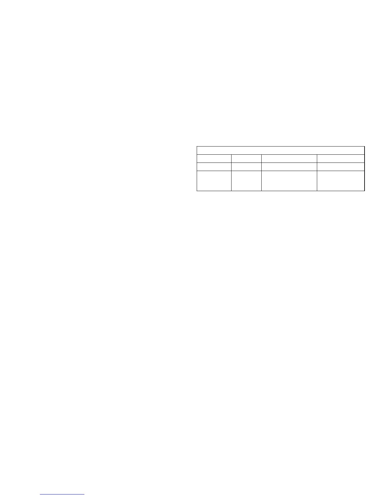
Flash Control
Name From Purpose Voltage
STB Charge IC404 Runs the Charge osc High = charging
STB Full Flash Unit Stops the Charge osc
si
nal. Turns on the
flash indicator light.
Low going pulse
When power is turned on in a camera mode (Still or Movie), IC404 brings
STB Charge line into the flash unit HIGH. This turns on the charge oscil-
lator in the flash unit. When the charge oscillator has charged the flash
capacitor to 300Vdc, the flash unit outputs a LOW going pulse on the
STB Full line to IC404. IC404 discontinues the positive voltage at the
STB Charge line and turns on the amber flash OK LED indicator inside
the flash button.
Floppy Disc Assembly
The floppy disc assembly is also not repairable and replaced as an as-
sembly. The assembly consists of two read/write heads (A and B), a
spindle motor to turn the disc, and a track stepping motor and feeler
switches to detect if a disc is present and if it is write protected. At power
ON if a disc is detected, the stepper motor moves to the initial position just
before the disc spins. The information is read from the disc from heads A
and B.
LCD Stage
The LCD panel is operational in all three modes (Play, Still or Movie). R,
G, B signals form a picture, supported by V and H sync from IC301 on the
main FC-72 board. The panel RGB signals are modified by LCD Driver
IC901 to set brightness, contrast and color level. The resultant output
signal is applied to the LCD unit.
The vertical and horizontal sync signals are applied to a timing generator
IC904. IC904 develops pulses for the LCD unit to locate the pixel group
that is applied the R, G or B signal.

 Loading...


