43
Spindle Motor Drive Signals
Signal Name Location
Voltage - Disc
not spinning
Comments
FPTS CN701/pin 18 5Vdc
HDS CN701/pin 17 4.8Vdc
FDD_Gnd CN701/pin 16 0Vdc
FDD_Gnd CN701/pin 15 0Vdc
Clock CN701/pin 14 0Vdc Rotation signal
MC CN701/pin 12 5Vdc
Index CN701/pin 11 5Vdc From drive
FDD_5V CN701/pin 10 5Vdc
FDD_5V CN701/pin 9 5Vdc
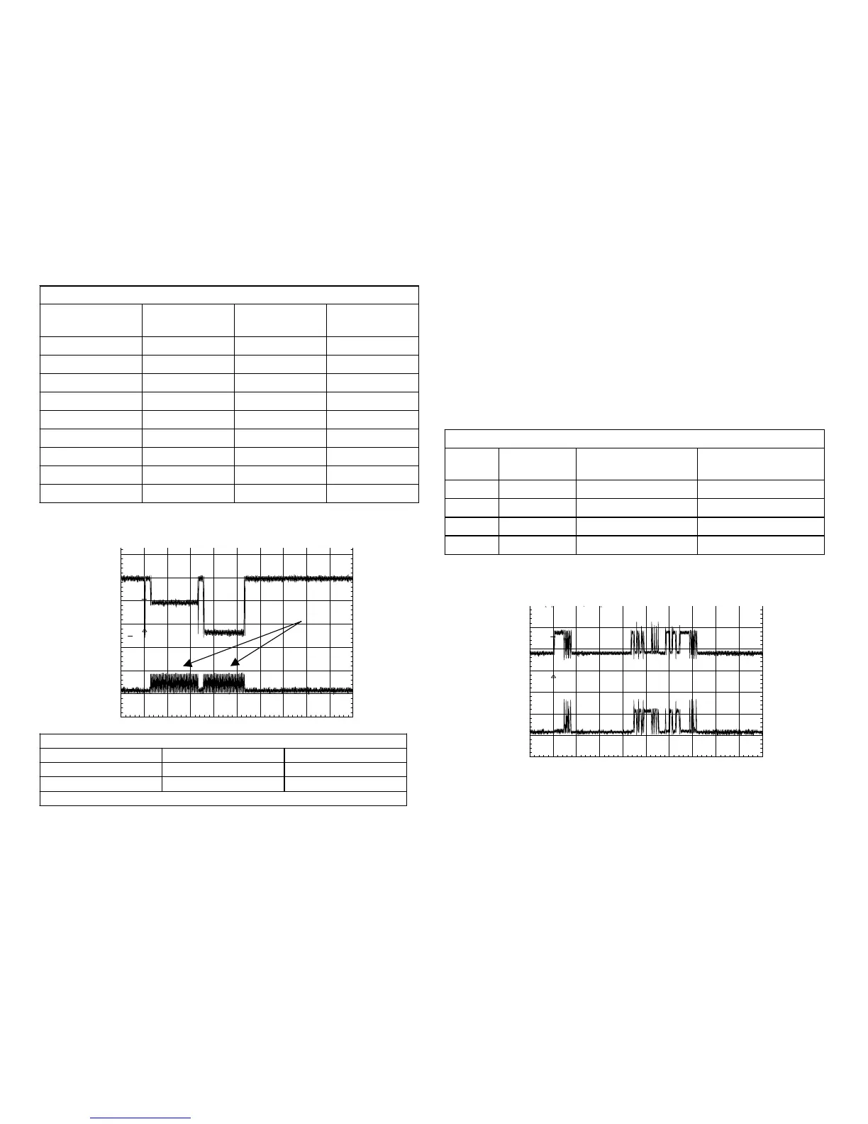
Spindle Motor Signals
Name Location Voltage
Index CN701/pin 11 5Vp-p
Clock CN701/pin 14 4Vp-p
Time Base = 1 second/div.
CH1!2.00 V= PKD
CH2!5.00 V= MTB1.00 s- 1.02dv ch1-
1
2
T
Spindle Motor
Drive Signal
(clock)
Index
Clock
Stepper Motor Drive
The stepper motor is connected to the read/write heads and can move
the heads from the outside track 00 to the inside data area of the floppy
disc. After a disc is detected, the spindle motor turns and the stepper
motor is instructed to move the heads to track 00.
Two out-of-phase stepper motor drive signals, from the main FC-72 board
are applied to motor coils A and B at CN701/pins 1-4 for movement. Each
motor coil that receives the signal is 16 ohms. All four signals must be
present for the stepper motor to rotate.
Stepper motor Dive Signals
Signal
Name
Location
Voltage no motor
movement
Description
PA CN701/pin 1 0Vdc + drive to coil A
PB CN701/pin 2 0Vdc + drive to coil B
PNA CN701/pin 3 0Vdc - drive to coil A
PNB CN701/pin 4 0Vdc - drive to coil B
The following waveforms show two of the four drive signals going to coils
A and coil B.

 Loading...


