5-5
1-3. CAMERA SYSTEM ADJUSTMENTS
1. HALL adjustment
(See original service manual page 5-13.)
: Changed points
21) Read DDS displayed data, and assume it as W
0. If W0 is in a
rage of “76 to 7A”, perform “processing after adjust-ment
finished”. If out of the range, make the following adjustment.
22) Convert W0 into decimal number to get W0’.
23) Calculate X2’ with the formulas given below (calculate decimal
numbers).
C’=W0’+K1’-W1’-21 ............................................. Formula 4
D’=K1’-W1’
X2’=
(100+D’)x(X
1’-48)+(48xC’)
................................ Formula 5
C’
(X
1’ is obtained from formula 3)
24) Convert X2’ into decimal number to get X2.
(Round off the decimal place.)
25) Set data: X2 to page: F, address: C7, and press the PAUSE button
on the adjustment remote commander.
26) Change the data on page: F, address: C8, so that DDS displayed
data is “78”.
27) Press the PAUSE button on the adjustment remote commander.
28) Set data: 01 to page: 2, address: 01, and press the PAUSE button
on the adjustment remote commander.
29) Confirm that DDS displayed data is in a range of “12 to 16”.
Processing after adjustment finished:
1) Set data: 00 to page: 2, address: 01, and press the PAUSE button
on the adjustment remote commander.
2) Set data: 00 to page: 0, address: 03.
3) Set data: 00 to page: 0, address: 01.
2. Flange back adjustment
The flange back of inner focus lens is adjusted auto-matically.
Flange back adjustment chart
Subject (2 m ± 5 mm position from lens front)
(Illuminance: 250 ± 50 lux)
Measurement point
Operation check on LCD screen
Measuring equipment
Adjustment page F
Adjustment address B6 to BB, BE to C5
Adjustment procedure:
1) Confirm that the center of flange back adjustment chart
coincides with the center of image screen with the zoom lens
at the TELE position and WIDE position respectively.
2) Set data: 01 to page: 0, address: 01.
3) Make sure that the data on page: F, address: B6 to BB, BE to
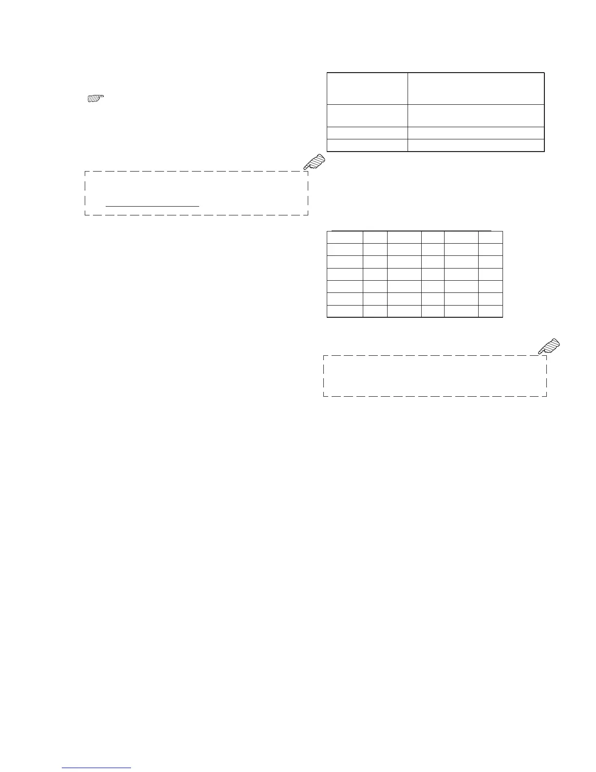
C5 are initial values listed in table below.
Address Data Address Data Address Data
B6 CD BE 00 C4 2E
B7 19 BF 00 C5 00
B8 92 C0 41
B9 21 C1 00
BA 12 C2 19
BB 14 C3 00
4) Confirm that the data on page: 2, address: 02 is “00”.
5) Set data: 13 to page: 2, address: 01, and press the PAUSE button
on the adjustment remote commander.
6) Set data: 15 to page: 2, address: 01, and press the PAUSE button
on the adjustment remote commander.
(The adjustment data are automatically entered to page: F,
address: B6 to BB, BE to C5.)
7) Confirm that the data on page: 2, address: 02 is “01”.
Processing after adjustment finished:
1) Set data: 00 to page: 2, address: 01, and press the PAUSE button
on the adjustment remote commander.
2) Turn off the main power supply (7.2 V).