Do you have a question about the Sony MVC-FD73 and is the answer not in the manual?
Details key differences between MVC-FD73 and MVC-FD71, including board additions.
Lists changes in board names for repair references, specifying old and new names.
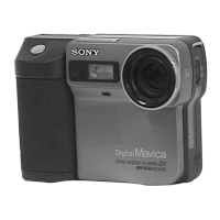
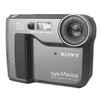
Identifies and illustrates key external parts of the camera for user reference.
Explains basic camera operations, button functions, and indicator meanings.
Provides a high-level overview of the camera's interconnected functional blocks.
Illustrates the camera's power supply circuit and distribution pathways.
Details the printed wiring for the complex FC-69 board, covering multiple functions.
Details the printed wiring for the PK-46 board, covering FDD, RGB, LCD, and key switch functions.
Outlines necessary preparations and equipment connections for camera adjustments.
Details the initialization procedures for E and F page data, including tables of addresses and values.
Step-by-step guide for performing the Hall effect adjustment on the camera system.
Details the automatic and manual procedures for adjusting the camera's flange back.
Details the procedure to adjust the D range of the LCD driver for correct display.
Specifies how to adjust the battery end voltage to ensure proper battery life.
Lists all electrical components for the PK-46 board with their part numbers and specifications.
Corrects procedures for Flange Back Adjustment and Picture Frame Setting.
| Optical zoom | 10x |
|---|---|
| Digital Zoom | 2x |
| Screen size | 2.5 inches |
| ISO Sensitivity | 100 |
| Camera type | Digital camera |
| Type | Digital Still Camera |
| Effective Pixels | 0.3 Megapixels |
| Storage Media | Floppy Disk |
| Storage | 1.44 MB |
| Focus Range | 20 in to infinity |
| Power Source | AA Batteries |