Do you have a question about the Sony MVC-FD91 and is the answer not in the manual?
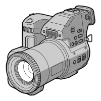
Identifies physical components, controls, and indicators on the camera.
Essential guidelines and warnings before operating the device.
Step-by-step instructions for fundamental camera functions like charging and recording.
Explains extended functionalities and settings for recording modes and functions.
Provides solutions for common camera issues, error codes, and warning messages.
Procedure for disassembling the Electronic Viewfinder and related board.
Steps for removing and disassembling the camera lens assembly.
Diagram illustrating the physical placement of various internal circuit boards within the camera.
High-level overview of the camera's internal system architecture and data flow.
Details the data interface and flow between the camera and floppy disk drive.
Overall schematic layout illustrating the camera's electronic component interconnections.
Illustrates the physical layout and component placement on the CCD imager board.
Physical layout of the FC-67 board, detailing component placement on side A.
Detailed circuit diagram for the camera's Y/C processing functionality.
Procedures for calibrating core camera functions, optical parameters, and sensors.
Steps to reset and initialize specific page data for adjustments.
Detailed procedures for adjusting specific camera systems like EVF and LCD.
Procedures for adjusting system control parameters such as battery end voltage.
Details the usage and operation of the remote commander for adjustments and data manipulation.
Explains data conversion between hexadecimal and decimal for adjustments.
How to enable diagnostic modes for testing and adjustment procedures.
Visual breakdowns of camera assemblies with part references for service.
Detailed illustration of the camera's rear cabinet and its components.
Comprehensive list of all electronic components, including part numbers and specifications.
| Brand | Sony |
|---|---|
| Model | MVC-FD91 |
| Category | Digital Camera |
| Language | English |