5-18
13-2. Steady Shot Adjustment (2)
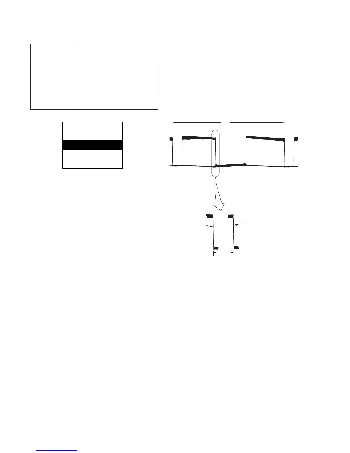
Subject Pattern B
(1.5m from the front of the protection
glass)
Measurement Point Pin 2 of CN701 of PK-45 board
(PANEL Y)
External trigger: Pin !¡ of CN701 of
PK-45 board (LANC IN)
Measuring Instrument Oscilloscope (V period)
Adjustment Page E
Adjustment Address AC
Fig. 5-1-14.
Adjusting method:
1) Expose pattern B with the zoom TELE end.
2) Adjust the inclination of the camera so that the horizontal black
line comes to the center of the screen.
3) Select page: 0, address: 01, and set data: 01.
4) Select page: E, address: BE, set data: 08, and press the pause
button of the adjustment remote commander.
5) Adjust to the falling edge of the waveform with vertical scale
on the oscilloscope. (Oscilloscope is V period).
6) Select page: E, address: BE, set data: 09, and press the pause
button of the adjustment remote commander.
At this time, measure the moving amount t2 (msec) of the falling
edge of the waveform.
7) Obtain DAC ’ using the following equation (decimal calculation).
DAC’ = (2.5/t2)×[1.00/ (SE201 sensor sensitivity)]×94
Note: The SE201 sensor sensitivity of the SE-78 board is labeled only
on the repair part.
8) Raise DAC’ to a whole number, convert it to a hexadecimal digit
and take this as DAC. (Refer to Table 5-2-1. “Hexadecimal -
Decimal conversion table” of “5-2. SERVICE MODE”.)
9) Select page: F, address: AC, set data: DAC, and press the pause
button of the adjustment remote commander.
10) Select page: E, address: BE, set data: 08, and press the pause
button.
Procedure after adjustment
1) Select page: 0, address: 01, and set data: 00.
2) Check that the steady shot operation is performed normally.
Fig. 5-1-15.
White
White
Pattern B
A4 size (297mm
×
210mm)
Black