6-6
251 3-713-786-21 SCREW (M2X3)
252 3-948-339-01 SCREW, TAPPING
253 1-671-878-11 FP-71 (CS-VP) FLEXIBLE BOARD
254 1-671-880-11 FP-73 (VP-FC) FLEXIBLE BOARD
255 1-671-879-11 FP-72 (SE-VP) FLEXIBLE BOARD
256 A-7073-751-A SE-78 BOARD, COMPLETE
257 A-7073-745-A CD-207 BOARD, COMPLETE
258 1-671-874-11 FP-67 (FC-CD) FLEXIBLE BOARD
259 3-947-268-11 TITE (2), +B TAPPING (P)
* 260 X-3949-137-1 ARM ASSY, VP
261 3-973-497-31 SCREW (M1.7), 0-NO. +P 2
262 3-709-461-01 VAP UNIT
263 3-052-979-01 FRAME (LOWER), LENS
264 3-957-990-11 ADAPTOR (C), CCD FITTING
265 1-758-217-11 FILTER BLOCK, OPTICAL
266 3-949-283-01 RUBBER (2), SEAL
267 A-7073-750-A VP-49 BOARD, COMPLETE
268 3-709-462-01 TUBE, MIRROR UNIT, MAIN
IC401 A-7030-955-A CCD BLOCK ASSY (CCD IMAGER)
a
a
not supplied
VCL-5214W
Screw tapping
(B tight)
1.7
×
4.5
(Note)
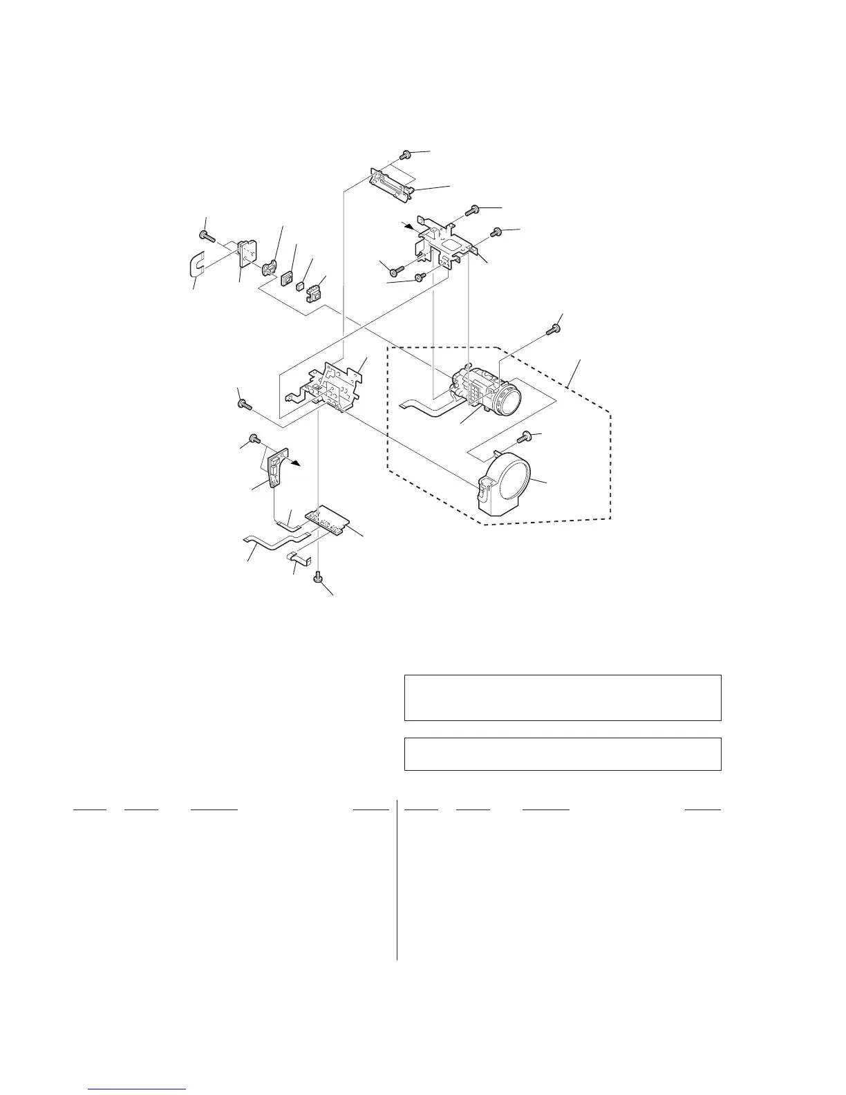
258
259
257
IC401
266
265
264
251
260
252
251
251
252
261
263
252
251
256
254
255
253
251
267
268
262
Ref. No. Part No. Description Remarks Ref. No. Part No. Description Remarks
6-1-6. LENS BLOCK SECTION
Be sure to read “Note on the CCD imager replacement” on
page 4-8 when changing the CCD Imager.
(Note) Never remove the motors from the lens block
because adjustments become necessary to
re-assemble them once they are removed.