5-11
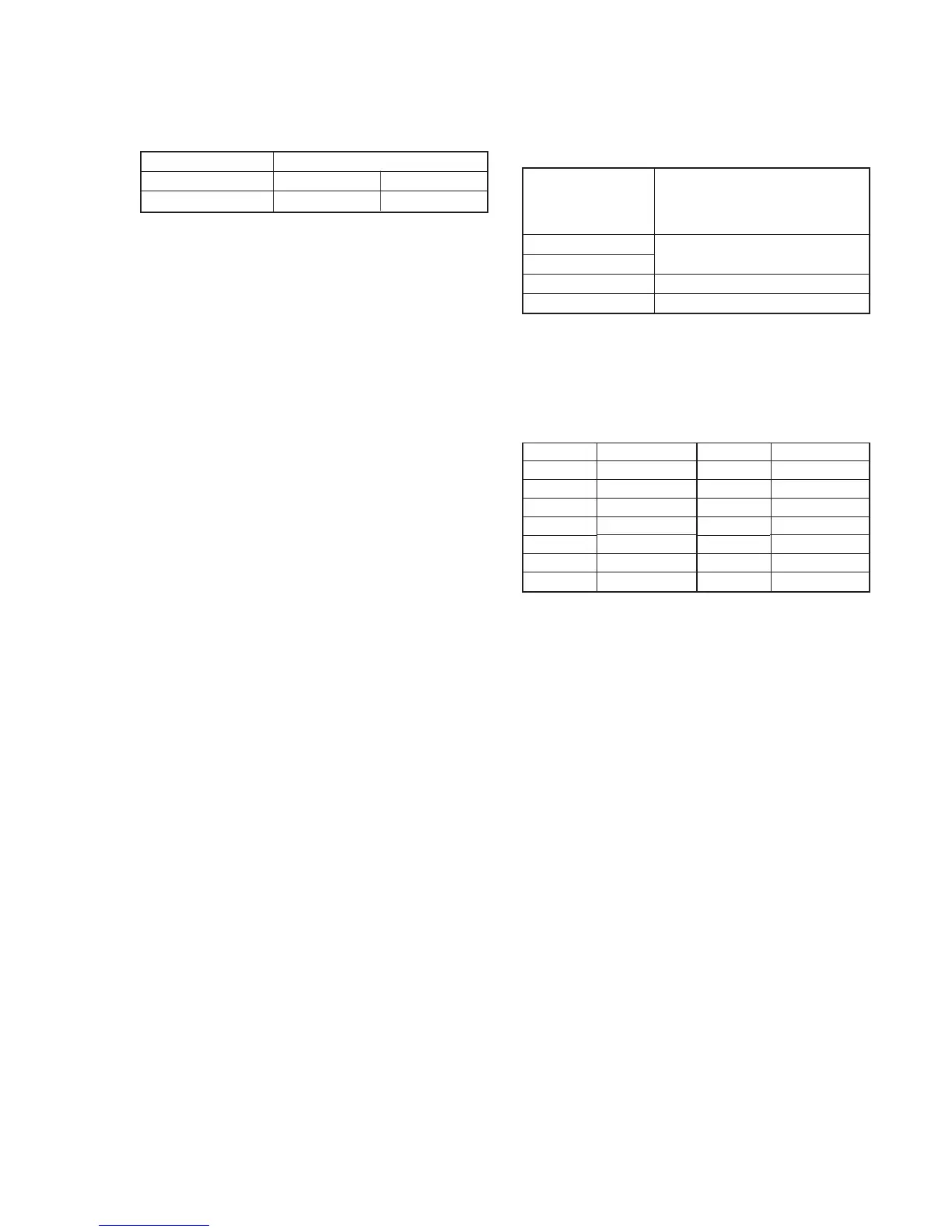
2. HALL Adjustment
For detecting the position of the lens iris, adjust the hall AMP gain
and offset.
Subject Not required
Adjustment Page F E
Adjustment Address C7, C8 1E
Note: Check that the data of page: 2, address: 02 is 00. If not, select page:
2, address: 01, set data: 00 and press the PAUSE button of the
adjustment remote commander.
Adjusting method:
1) Select page: 0, address: 01, and set data: 01.
2) Select page: 2, address: 01, set data: 6D, and press the PAUSE
button of the adjustment remote commander. (The HALL
adjustment is performed and the adjustment data is stored in
page: F, address: C7, C8 and page: E, address: 1E.)
3) Select page: 2, address: 02, and check that the data is “01”.
Processing after Completing Adjustments
1) Select page: 2, address: 01, set data: 00, and press the PAUSE
button of the adjustment remote commander.
2) Select page: 0, address: 01, and set data: 00.
3. Flange Back Adjustment
The inner focus lens flange back adjustment is carried out
automatically. In whichever case, the focus will be deviated during
auto focusing/manual focusing.
Subject Flange back adjustment chart
(2.0 m from the front of the protection
glass)
(Luminance: 350 ± 50 lux)
Measurement Point Check operation on LCD screen
Measuring Instrument
Adjustment Page F
Adjustment Address B6 to BB, BE to C5
Adjusting method:
1) Check that at both the zoom lens TELE end and WIDE end,
the center of the chart for the flange back adjustment and center
of the exposure screen coincide.
2) Select page: 0, address: 01, and set data: 01.
3) Check that the data of page: F, address: B6 to BB, BE to C5 is
the initial value (See table below).
4) Select page: 2, address: 02, and check that the data is “00”.
5) Select page: 2, address: 01, set data: 13, and press the PAUSE
button of the adjustment remote commander.
6) Select page: 2, address: 01, set data: 15, and press the PAUSE
button of the adjustment remote commander.
(The adjustment data will be automatically input to page: F,
addresses: B6 to BB, BE to C5.)
7) Select page: 2, address: 02, and check that the data is “01”.
Processing after Completing Adjustments
1) Select page: 2, address: 01, set data: 00, and press the PAUSE
button of the adjustment remote commander.
2) Select page: 0, address: 01, and set data: 00.
Address
B6
B7
B8
B9
BA
BB
BE
Address
BF
C0
C1
C2
C3
C4
C5
Data
56
19
E0
21
E7
11
00
Data
00
23
00
19
00
11
00

 Loading...