2-3
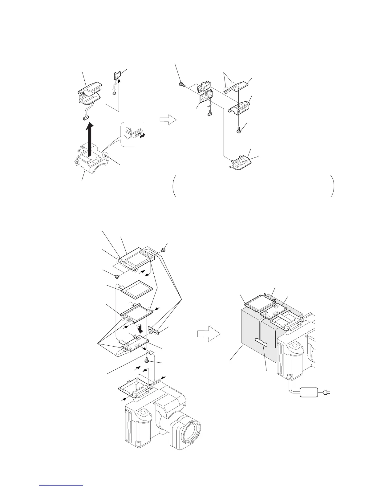
2-4. CABINET (ST) ASSEMBLY, FLASH UNIT, MA-348 BOARD
2-5. LCD UNIT, PD-104 BOARD
[LCD CHECK SERVICE POSITION]
!£
FLASH unit
1
Remove the claw
3
Slide the knob in the
direction of the arrow
a
to raise the flash
unit.
Note : Before starting to disassemble, confirm how harnesses are routed.
When re-assembling the parts, route the harnesses in the original
position. If the harnesses are not routed corrected, it can break down
the harnesses when the Cabinet (ST) assembly is re-assembled.
2
MA-348 board
(Note)
4
Cabinet (upper) (POP)
assembly
5
Cabinet (ST) assembly
6
Two tapping screws (B2
×
5)
7
Remove the claw
8
ST blind cabinet
9
Tapping screw (B2
×
5)
!º
Remove the claws
!¡
Cabinet (upper) (POP)
!™
Cabinet (lower) (POP) assembly
a
a
c
d
a
b
d
c
b
PD-104
0
Slide the board
in the direction
of the arrow
e
to disengage the
claws.
1
Screws (M1.4)
2
Screws (M1.4)
When re-assembling
put in the LCD this
side before.
5
Screw (M2
×
3)
6
Remove
the claws
3
Remove the claw
7
FP-70 flexible
FP-70 flexible
4
Remove the FP-69 flexible
8
P cabinet (front) assembly
9
Remove
the claws
!¡
LCD
!™
Cold cathode
florescent tube
!£
PD-104 board
e
Back light
(Cold cathode florescent tube)
PD-104 board
LCD
AC IN
AC
ADAPTOR
Base
(Use box or the like.)

 Loading...