5-14
8. Color Reproduction Adjustment
Adjust the color separation matrix coefficient so that proper color
reproduction is produced.
Subject Color bar chart standard picture frame
Measurement Point CHX: Pin 1 of CN701 of PK-45
board (PANEL B-Y)
CHY: Pin 3 of CN701 of PK-45
board (PANEL R-Y)
Measuring Instrument Oscilloscope (X-Y mode)
Adjustment Page E
Adjustment Address 23, 24, 25, 26, 27, 28, 29. 2A
Specified Value All color luminance points should
settle within each color reproduction
frame.
Note 1: This adjustment should be carried out upon completion of “6. Auto
White Balance Standard Data Input”.
Switch setting:
1) FINDER/LCD ................................................................. LCD
Preparations before adjustments
1) Set to the PLAY mode.
2) Playback the color bar signal (MVC-001C.JPG) of the
alignment disk (TFD2-1(+) or TFD2-2(–)).
3) Select page: 0, address: 01, and set data: 01.
4) Select page: 3, address: 02, and set data: 01.
5) Select page: F, address: E0, set data: 40, and press the PAUSE
button of the adjustment remote commander.
6) Adjust the X POSITION and Y POSITION of the oscilloscope,
and adjust the black luminance point to the center of the CRT
screen.
7) Adjust the Xch GAIN and Ych GAIN of the oscilloscope, and
settle each color luminance point in each color reproduction
frame (frame of the thin line).
8) Repeat steps 6) to 7) until each color luminance point settled
in each color reproduction frame (frame of the thin line).
9) Set to the camera (STILL) mode.
Adjusting method:
1) Select page: 0, address: 01, and set data: 01.
2) Select page: 2, address: 10, and set data: 59.
3) Select page: 2, address: 01, set data: 0F, and press the PAUSE
button.
4) Adjust the X POSITION and Y POSITION of the oscilloscope,
and adjust the black luminance point to the center of the CRT
screen.
5) Change the data of page: E, address: 23, 24, 27 and 28, and
settle the yellow and blue luminance points in each color
reproduction frame (frame of the thick line).
Note 2:Be sure to press the PAUSE button of the adjustment remote
commander before changing the addresses. If not, the new
data will not be written to the memory.
6) Adjust the X POSITION and Y POSITION of the oscilloscope,
and adjust the black luminance point to the center of the CRT
screen.
7) Change the data of page: E, address: 25, 26, 29 and 2A, and
settle the red, magenta,cyan and green luminance points in each
color reproduction frame (frame of the thick line).
Note 2:Be sure to press the PAUSE button of the adjustment remote
commander before changing the addresses. If not, the new
data will not be written to the memory.
8) Repeat steps 4) to 7) until all color luminance point settled
within each color reproduction frame (frame of the thick line).
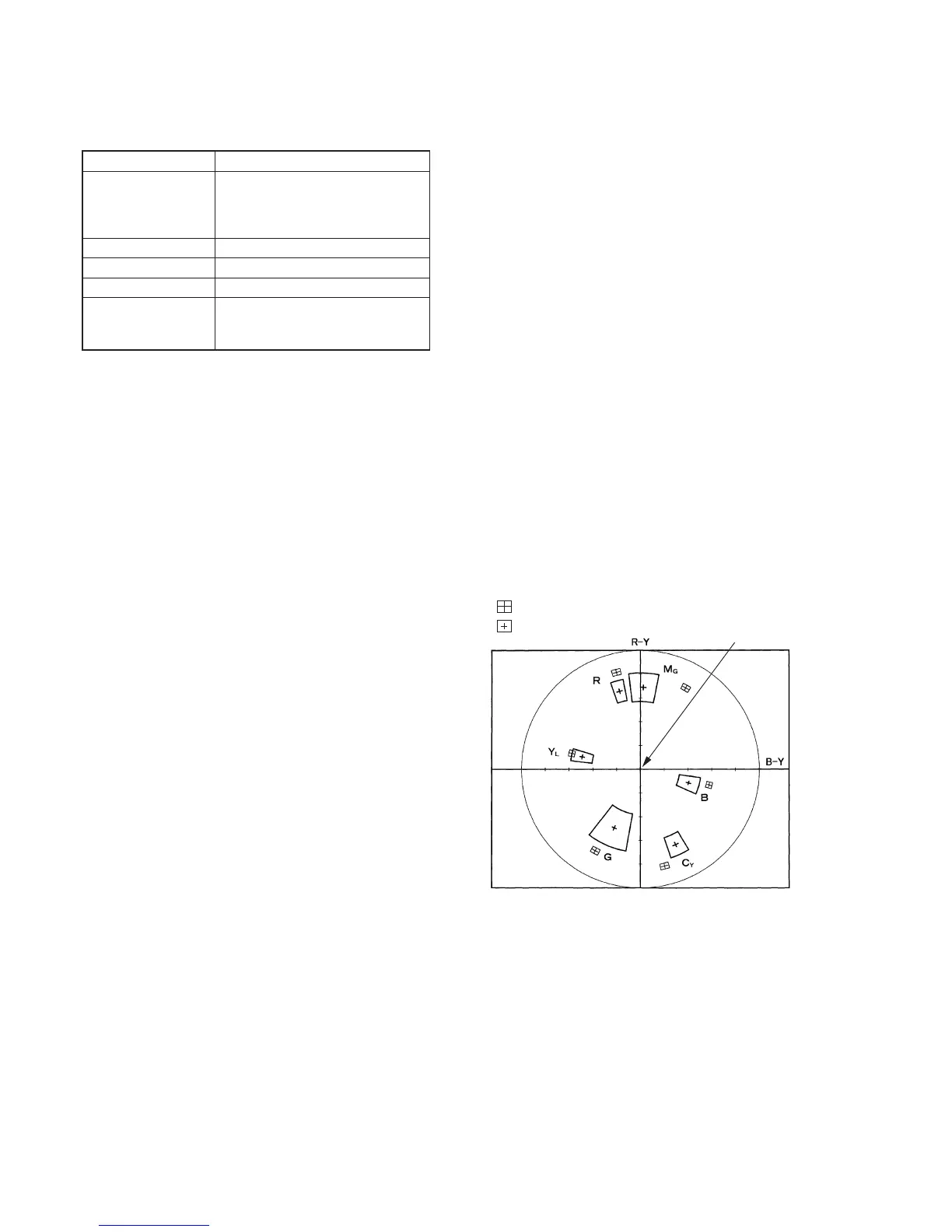
Fig. 5-1-11.
Processing after Completing Adjustments
1) Select page: F, address: E0, set data: 1B, and press the PAUSE
button .
2) Select page: 0, address: 01, set data: 00.
3) Select page: 2, address: 01, and set data: 00, and press the
PAUSE button .
4) Select page: 2, address: 10, set data: 00.
5) Select page: 3, address: 02, and set data: 00.
Black luminance point
: For preparation
: For adjustment