2-1
MVC-FD91
SECTION 2
DISASSEMBLY
NOTE: Follow the disassembly procedure in the numerical order given.
NOTE: Follow the disassembly procedure as shown in the flow chart below.
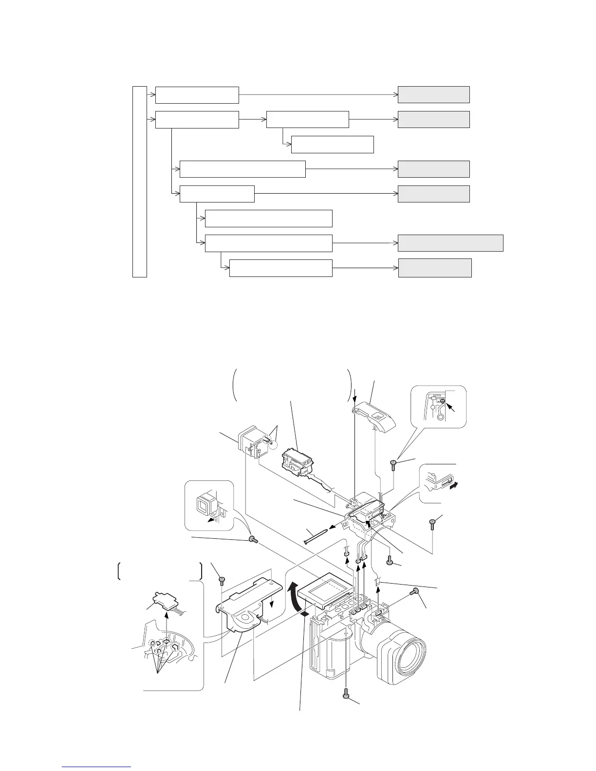
2-1. EVF BLOCK (1), RL-52 BOARD
MVC-FD91 MAVICA
2-5.
2-9.
2-1. 2-2.
2-3.
2-4.
2-6.
2-7.
2-8.
LCD unit,
PD-104 board
EVF block (1),
RL-52 board
EVF block (2)
VF-131 board
Cabinet (ST) assembly,
FLASH unit, MA-348 board
LENS block
CD-207 board, VP-49 board,
SE-78 board
FC-67 board, DD-119 board
PK-45 board,
FDD block assembly
LCD check
Service position
EVF check
Service position
LENS unit check
Service position
MAIN (FC-67) board check
Service position
Overall check
Service position
FLASH UNIT
replacement
a
a
!£
Remove
the claws
1
Two screws (M2
×
4),
lock ace, P2
2
Tapping screw (B2
×
5)
3
Cabinet (RL) assembly
Cabinet (ST)
assembly
(See page 2-3)
4
Cabinet (microphone) assembly
5
Shaft (POP)
8
Screw (M2
×
4),
lock ace, P2
9
Pull up the LCD block assembly
0
Screw (M2
×
4),
lock ace, P2
!¡
FP-68 flexible
board (21P)
!™
Screw (M1.7)
!¢
Cabinet (EVF) assembly
!∞
EVF block
Remove the FP-68 flexible board
from the cabinet (ST) assembly
with care so that the board must
not be caught.
RL-52 board
Claws
In case of removing
the RL-52 board
6
Pull the knob
in the direction
of the arrow.
8
Screw (M2
×
4)
8
Screw (M2
×
4)
7
Open the flash lid.