5-26
Fig. 5-1-21. Fig. 5-1-22.
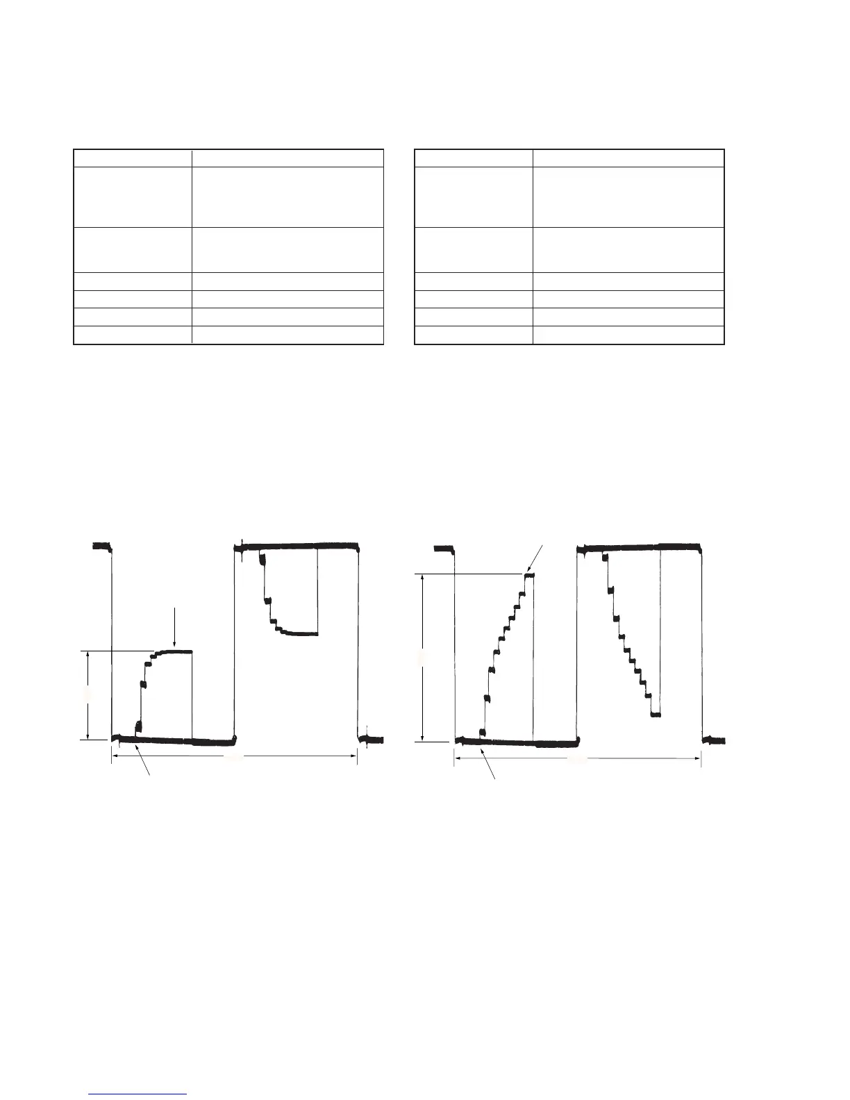
4. Bright Adjustment (PK-45 board)
Set the level of the VIDEO signal for driving the LCD to the specified
value. If deviated, the screen image will be blackish or saturated
(whitish).
Mode Playback
Signal Alignment disk (TFD2-1(+) or TFD2-
2(–)):
Stair step signal of 10 steps (MVC-
006T.JPG)
Measurement Point Pin 9 of CN701 (VG)
External trigger: Pin 8 of CN701
(COM)
Measuring Instrument Oscilloscope
Adjustment Page F
Adjustment Address 30
Specified Value A = 2.00 ± 0.05V
Adjusting method:
1) Select page: 0, address: 01, and set data: 01.
2) Select page: 3, address: 02, and set data: 01.
3) Select page: 3, address: 19, and set data: 08.
4) Select page: F, address: 30, change the data and set the voltage
(A) between the pedestal and white level to the specified value.
5) Press the PAUSE button of the adjustment remote commander.
6) Select page: 3, address: 02, and set data: 00.
7) Select page: 3, address: 19, and set data: 00.
8) Select page: 0, address: 01, and set data: 00.
5. Contrast Adjustment (PK-45 board)
Set the level of the VIDEO signal for driving the LCD to the specified
value. If deviated, the screen image will be blackish or saturated
(whitish).
Mode Playback
Signal Alignment disk (TFD2-1(+) or TFD2-
2(–)):
Stair step signal of 10 steps (MVC-
006T.JPG)
Measurement Point Pin 9 of CN701 (VG)
External trigger: Pin 8 of CN701
(COM)
Measuring Instrument Oscilloscope
Adjustment Page F
Adjustment Address 34
Specified Value A = 3.05 ± 0.07V
Adjusting method:
1) Select page: 0, address: 01, and set data: 01.
2) Select page: 3, address: 02, and set data: 01.
3) Select page: F, address: 34, change the data and set the voltage
(A) between the 0 IRE (pedestal) and 100 IRE to the specified
value.
4) Press the PAUSE button of the adjustment remote commander.
5) Select page: 3, address: 02, and set data: 00.
6) Select page: 0, address: 01, and set data: 00.
Pedestal
A
2H
White
0 IRE
100 IRE
A
2H