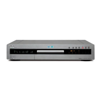
RDR-GX220/GX330
For schematic diagrams:
• All capacitors are in µF unless otherwise noted. pF : µµF.
50V or less are not indicated except for electrolytics and
tantalums.
• All resistors are in ohms, 1/4W (Chip resistors : 1/10W)
un-less otherwise specified.
kΩ = 1000Ω, MΩ = 1000kΩ.
• Caution when replacing chip parts.
New parts must be attached after removal of chip.
Be careful not to heat the minus side of tantalum capacitor,
because it is damaged by the heat.
• All variable and adjustable resistors have characteristic
curve B, unless otherwise noted.
• : non flammable resistor.
• : fusible resistor.
• : panel designation.
• f : internal component.
• : adjustment for repair.
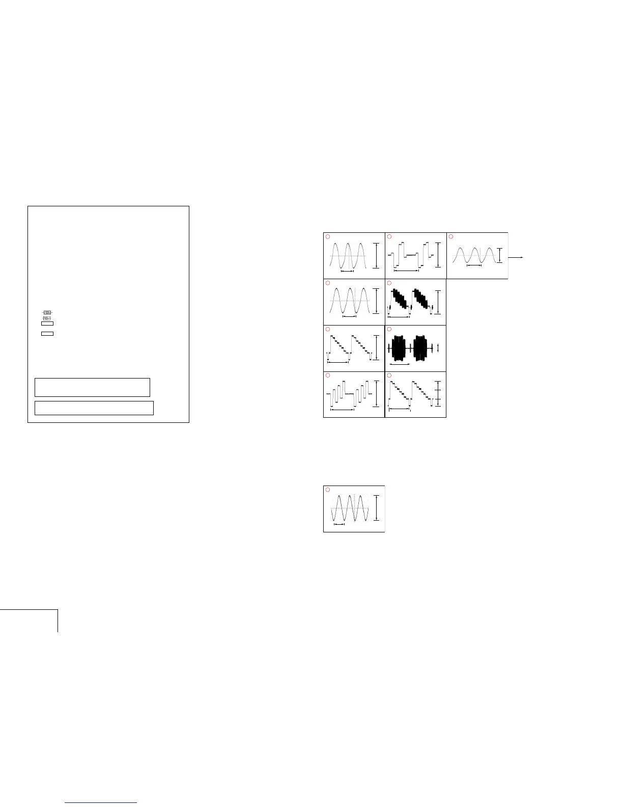
• Circled numbers refer to waveforms.
• Voltages are dc between measurement point.
• Readings are taken with a color-bar signal on DVD refer-
ence disc and when playing CD reference disc.
• Readings are taken with a digital multimeter (DC 10MΩ).
• Voltage variations may be noted due to normal production
tolerances.
4-2. SCHEMATIC DIAGRAMS
THIS NOTE IS COMMON FOR SCHEMATIC DIAGRAMS
(In addition to this, the necessary note is printed in each block)
WAVEFORMS
AV-100 BOARD
4-3 4-4
WAVEFORMS
AV-100/RD60
When indicating parts by reference number, please include
the board name.
Note : The components identified by mark 0 or dotted
line with mark 0 are critical for safety.
Replace only with part number specified.
2Vp-p
H
2Vp-p
H
H
572 mVp-p
(NTSC)
600 mVp-p
(PAL)
H
1.4Vp-p
J701 COMPONENT PR (C/BAR PB)*
5
54.3 ns
3.5Vp-p
X1401 6
RDR-GX220 ONL
 Loading...