10
Zoom:
Turn the ZOOM ring on the upper part
of the joystick clockwise to make the
subject larger (zoom in). Turn it
counterclockwise to make the subject
smaller (zoom out).
For an ILME-FR7 target camera, you can
switch the joystick function to the screen
display operation on the camera image
using the CAM GUI / P/T RST (pan/tilt reset)
button. For details, see “Operating with the
Screen Display Overlaid
on the Camera
Image (CAM GUI Operation Mode) (ILME-
FR7)” (page 50).
-a Joystick button
Press and hold to return the orientation of
the
camera to face the front.
For an ILME-FR7 target camera, it functions
as
the apply button in CAM GUI operation
mode.
-b ZOOM ring
Controls the zoom.
For details, see “To control the zoom using
the ZOOM ring on the top of the joystick”
(page 36).
PAN-TILT SPEED knob
Adjusts the speed of pan/tilt operations in
r
esponse to the joystick.
For details, see “To adjust the pan/tilt speed”
(page 35).
CAM GUI / P/T RST (pan/tilt reset) button
Press and hold the button to reset the pan/
ti
lt position of the target camera.
For an ILME-FR7 target camera, press the
b
utton to switch the joystick function as
follows.
ACTIVE button
Enables/disables operation of the joystick
co
ntrol block.
When the button is turned on (button is lit),
o
peration of the joystick control block
becomes enabled.
When the button is turned off (button is not
li
t), operation of the joystick control block
becomes disabled.
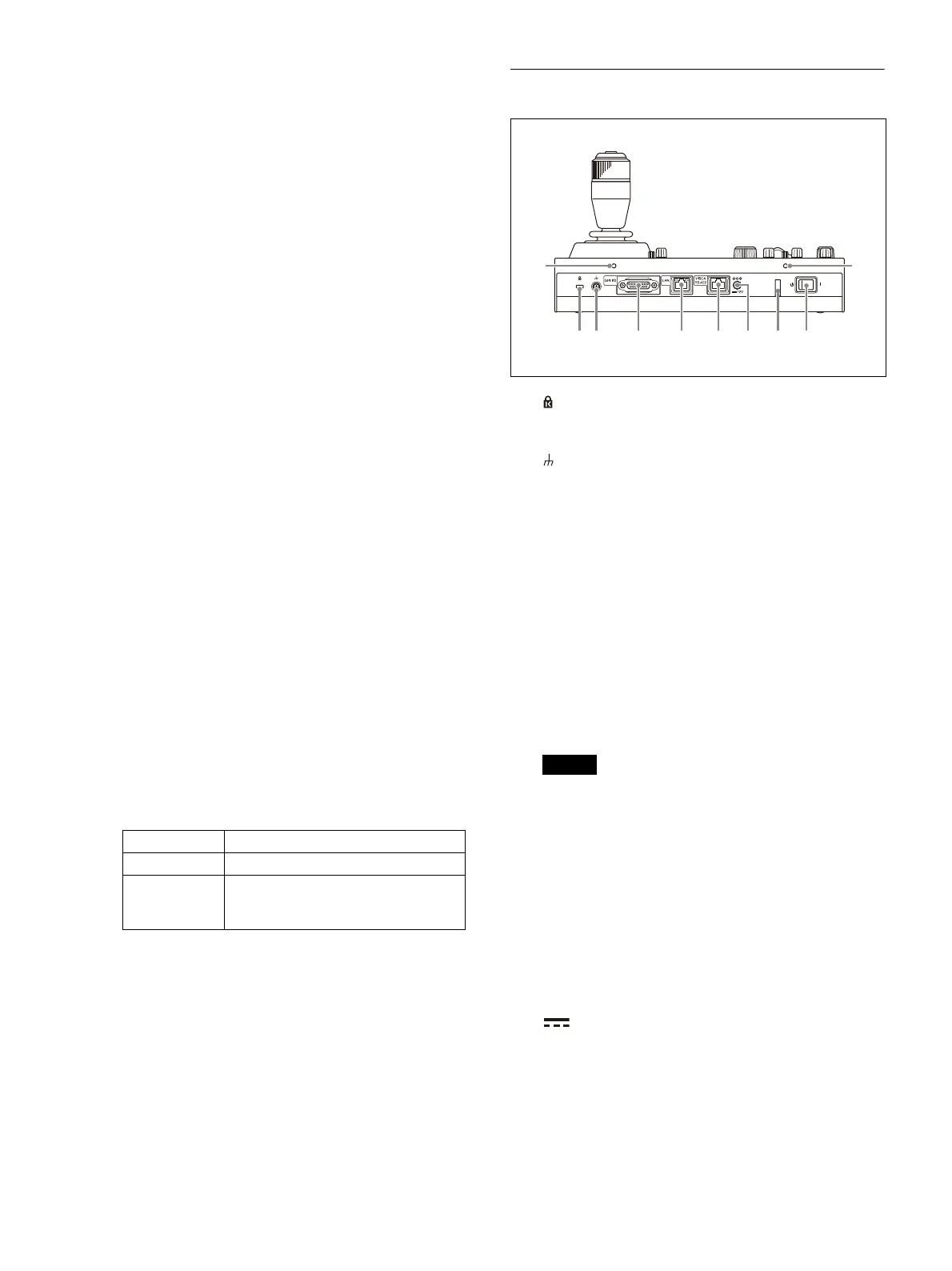
Rear
Anti-theft wire attachment point
Attach a wire to prevent theft.
Ground connection
GPI I/O connector
Used as a tally input from an external device
o
r as a contact output connector of the
selected camera number.
LAN (network) connector (RJ-45)
Use for LAN connection.
Connect a LAN hub (10BASE-T/100BASE-TX)
u
sing a LAN cable (category 5 or higher).
When a link is established, the green
ind
icator lights, and it blinks during
communication. For 100BASE-TX
connections, the yellow indicator lights.
Notes
• For safety, do not connect the connector
for peripheral device wiring that might
have excessive voltage to this port. Follow
the instructions for this port.
• When you connect the LAN cable of the
u
nit to peripheral device, use a shielded-
type cable to prevent malfunction due to
radiation noise.
VISCA RS-422 OUT connector (RJ-45)
Used for VISCA RS-422 serial connection.
12 V (DC power supply input)
connector
Connect to an AC power adapter (sold
se
parately).
Button state Function
Not lit Pan and tilt control
Lit Screen display operation overlaid
o
n the camera image.
(CAM GUI operation mode)
ȫ Ȭ ȭ ȯ ȰȩȪ
ȱ
ȱ
Ȯ