4-8
BDP-BX39/S390
1
A
B
C
D
E
F
G
H
I
J
2
12
13
11
10
98765
43
14
The components identifi ed
by mark
or dotted line with
mark
are critical for safety.
Replace only with part number
specifi ed.
4-8
.
MB-
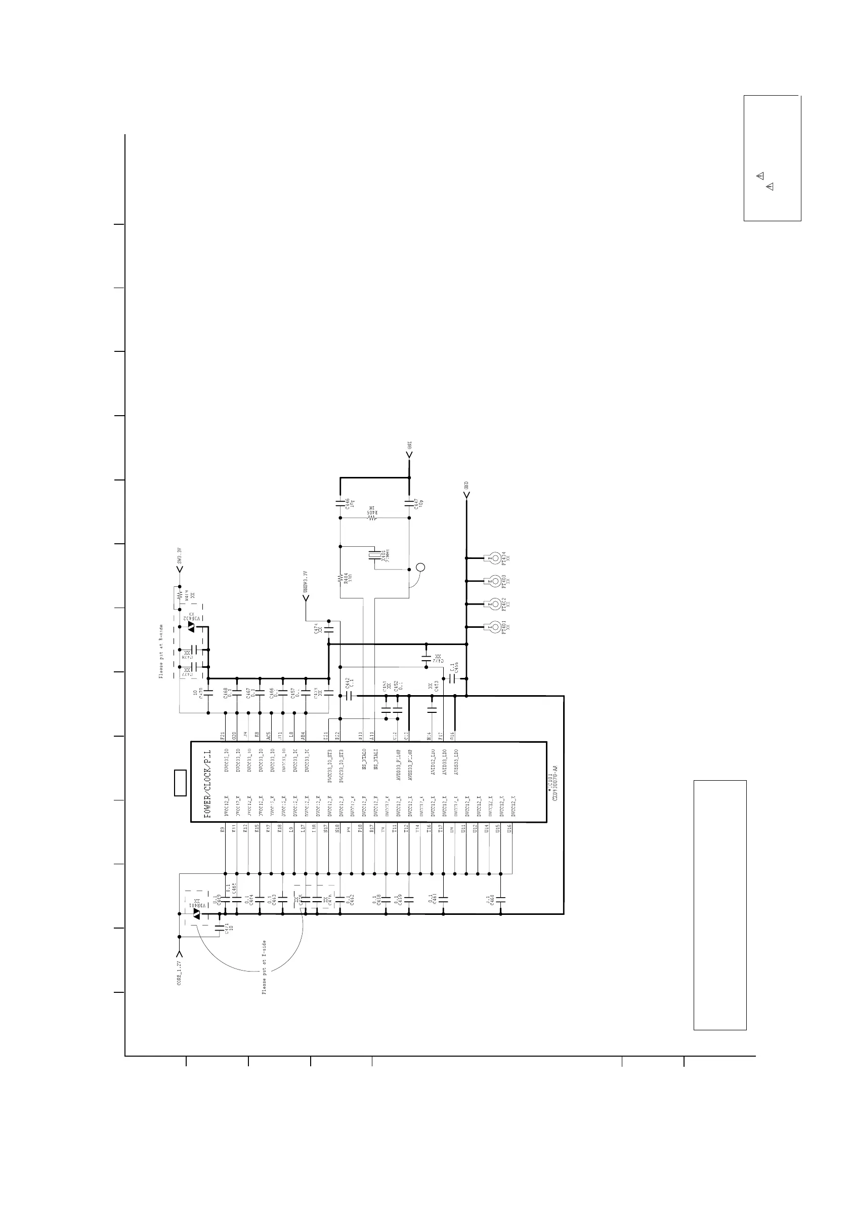
144 BOARD
(
CLK/POWER2) SCHEMATIC DIAGRAM (4/12)
- Ref. No.: MB-144 board; 10,000 series
IC101
•
See page 5-3/5-4 for printed wiring board.
Notes:
MB-144 mounted PWB must be replaced if
IC101 (MAIN) and IC501 (NAND FLASH)
is damaged or not functioning.
The old MB-144 mounted PWB must be completely disposed.
2


 To Next Page