EasyManua.ls Logo

Sony RMT-V501D User Manual

Sony RMT-V501D
121 pages
To Next Page IconTo Next Page
Page #1 background imageLoading...
Page #1 background image
US Model
SERVICE MANUAL
DVD PLAYER/
VIDEO CASSETTE RECORDER
SPECIFICATIONS
General
Power requirements
120 V AC, 60 Hz
Power consumption
25 W
Power back-up
Back-up duration: 0 min
Operating temperature
0°C to 45°C (32°F to 113°F)
Storage temperature
-20°C to 60°C (-4°F to 140°F)
Operating humidity
25% to 80%
Dimensions including projecting parts and controls
(w/h/d)
Approx. 430 × 85 × 287 mm
(Approx. 17 × 3.4 × 11.5 inches)
Mass
Approx. 3.6 kg (Approx. 7.9 lbs)
Supplied accessories
Remote commander (1)
Size AA (R6) batteries (2)
75-ohm coaxial cable with F-type connectors (1)
Audio/video cord (pinplug × 3 y pinplug × 3) (1)
Design and specifications are subject to change without
notice.
System
Laser
Semiconductor laser
Format
VHS NTSC standard
Video recording system
Rotary head helical scanning FM system
Video heads
Double azimuth four heads
Video signal
NTSC color, EIA standards
Tape speed
SP: 33.35 mm/s (1
inches/s)
EP: 11.12 mm/s (
inches/s)
LP: 16.67 mm/s (
inches/s),
playback only
Maximum recording/playback time
8 hrs. in EP mode (with T-160 tape)
Rewind time
Approx. 1 min (with T-120 tape)
Tuner section
Channel coverage
VHF 2 to 13
UHF 14 to 69
CATV A-8 to A-1, A to W, W+1 to W+84
Antenna
75-ohm antenna terminal for VHF/UHF
Inputs and outputs
LINE IN 1 and LINE-2 IN
VIDEO IN, phono jack (1 each)
Input signal: 1 Vp-p, 75 ohms, unbalanced, sync
negative
AUDIO IN, phono jacks (2 each)
Input level: 327 mVrms
Input impedance: more than 47 kilohms
LINE OUT
VIDEO OUT, phono jack (1)
Output signal: 1 Vp-p, 75 ohms, unbalanced, sync
negative
AUDIO OUT, phono jacks (2)
Standard output: 327 mVrms
Load impedance: 47 kilohms
Output impedance: less than 10 kilohms
DIGITAL OUT
OPTICAL, Optical output jack
-18 dBm (wave length: 660 nm)
COAXIAL, phono jack
Output signal: 0.5 Vp-p, 75 ohms
COMPONENT VIDEO OUT (Y, Pb, Pr)
Phono jack
Y: 1.0 Vp-p/Pb, Pr: 0.7 Vp-p, 75 ohms
S-VIDEO OUT
4-pin, mini-DIN jack
Y: 1.0 Vp-p, unbalanced, sync negative
C: 0.286 Vp-p, load impedance 75 ohms
Timer section
Clock
Quartz locked
Timer indication
12-hour cycle
Timer setting
8 programs (max.)
3
8
7
16
11
16
TS-10 MECHANISM
SLV-D350P/D550P
RMT-V501C/V501D
Photo: SLV-D550P
RMT-V501D
ENERGY STAR
¤
is a U.S. registered mark.
As an ENERGY STAR
¤
Partner, Sony Corporation has
determined that this product meets the ENERGY STAR
¤
guidelines for energy efficiency.
Refer to the SERVICE MANUAL of VHS MECHANI-
CAL ADJUSTMENT MANUAL VII for MECHANICAL
ADJUSTMENTS. (9-921-790-11)

Table of Contents

Question and Answer IconNeed help?

Do you have a question about the Sony RMT-V501D and is the answer not in the manual?

Sony RMT-V501D Specifications

General IconGeneral
BrandSony
ModelRMT-V501D
CategoryDVD Player
LanguageEnglish

Summary

SPECIFICATIONS

System

Laser, VHS format, video recording system, tape specs.

Tuner section

Channel coverage and antenna specs.

Inputs and outputs

Audio/video connections and signal characteristics.

DIGITAL OUT

Digital audio output formats and connections.

S-VIDEO OUT

S-Video output connection and signal specs.

Timer section

Clock and program setting info.

General

Power, temp, dimensions, mass, accessories.

SAFETY CHECK-OUT

LEAKAGE TEST

Test AC leakage current on exposed metal parts.

SAFETY PRECAUTIONS

Pre-Servicing Checks

Checks before returning the instrument to the customer.

Leakage Current Tests

Procedures for hot and cold leakage current tests.

SERVICING PRECAUTIONS

General Servicing Precautions

General guidelines for servicing.

Insulation Checking Procedure

Steps to check unit insulation resistance.

ESD PRECAUSIONS

Electrostatically Sensitive Devices (ESD)

Procedures to reduce static damage to ESD devices.

HANDLING THE OPTICAL PICK-UP

Handling Procedure

Recommended method for handling the optical pick-up safely.

PICK-UP DISASSEMBLY AND REASSEMBLY

Disassembly

Steps for disassembling the pick-up.

Assembly

Steps for reassembling the pick-up.

Getting Started

Unpacking

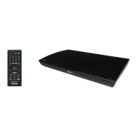
Check all items received with the DVD-VCR.

Setting up the remote commander

Insert batteries and learn basic remote operation.

Controlling other TVs with the remote commander

Program remote for non-Sony TVs using code numbers.

Basic hookups

Connect DVD-VCR to TV and other equipment.

Advanced Hookups

A/V Receiver hookup

Connect DVD-VCR to A/V receiver for surround sound.

S-Video/Component Video hookup

Connect DVD-VCR to TV using S-Video or Component Video.

DVD Settings and Adjustments

Audio Setup

Configure sound settings for playback and connections.

Screen Setup

Adjust screen settings like aspect ratio and black level.

Progressive Setting

Enable progressive scan for improved picture quality.

Display and Sound Track Language

Set languages for DVD menus, audio, and subtitles.

Parental Control

Setting Playback Limitations

Set playback limitations based on age ratings.

Changing the Password

Procedures for changing or resetting the parental control password.

DVD Additional Operations

Program Play

Create custom playback sequences by programming track order.

Shuffle Play

Play tracks in a random, shuffled order.

Repeat Play

Play titles, chapters, or tracks repeatedly.

Playing MP3 Audio Tracks

Play MP3 audio files from DATA CDs.

Playing JPEG Image Files

Display JPEG image files from DATA CDs.

Playing VIDEO CDs

PBC ON/OFF Functions

Use PBC for interactive playback or turn it off for continuous play.

VCR Additional Operations

Quick Timer Recording

Set up automatic recording for up to eight programs.

Searching using various functions

Find tape points via index, counter, or blank search.

Adjusting the picture (tracking)

Manually adjust tracking for better picture quality.

Changing menu options

Configure VCR settings like tape length and auto play.

Disassembly and Reassembly

Cabinet and PCB

Procedures for removing cabinet and PCB components.

Circuit Board Locations

Identifies locations of VCR Main PCB, DVD Main PCB, and Function PCB.

VCR Deck Parts Locations

Diagrams showing top and bottom views of VCR deck components.

VCR DECK Component Removal

Specific procedures for removing VCR deck parts like levers and gears.

PRINCIPAL PARTS Maintenance

Cleaning, Lubrication, and Replacement Time

Table detailing maintenance intervals for key parts.

DVD DECK Disassembly

DVD Deck Component Removal

Procedures for removing DVD deck parts like chuck, tray, P/U deck, housing, and bracket.

BLOCK DIAGRAM

System Signal Flow

Illustrates the overall system architecture and signal flow.

PCB DIAGRAMS

VCR Main/Function-Timer PCB Layout

Component and conductor side layouts for the VCR main board.

DVD Main PCB Layout

Component and conductor side layouts for the DVD main board.

Dial-Timer PCB Layout

Layouts for the Dial-Timer PCB specific to the D550P model.

SCHEMATIC DIAGRAMS

VCR Main PCB Schematics

Detailed circuit diagrams for VCR main board sections.

DVD Main PCB Schematics

Detailed circuit diagrams for DVD main board sections.

ALIGNMENT AND ADJUSTMENTS

VCR Adjustment Procedures

Procedures for X-Point, Head Switching, and NVRAM adjustments.

TROUBLESHOOTING

No Power / Remote Control Error

Flowchart for diagnosing power and remote control issues.

VCR Play Mode Issues

Flowchart for troubleshooting VCR play mode failures.

VCR Record Mode Issues

Flowchart for troubleshooting VCR record mode failures.

VCR Fast Forward Issues

Flowchart for troubleshooting fast forward issues.

REPAIR PARTS LIST

Exploded Views

Diagrams showing parts breakdown for assemblies.

Electrical Parts List

List of electronic components with part numbers.

Related product manuals