7-3 7-4 E
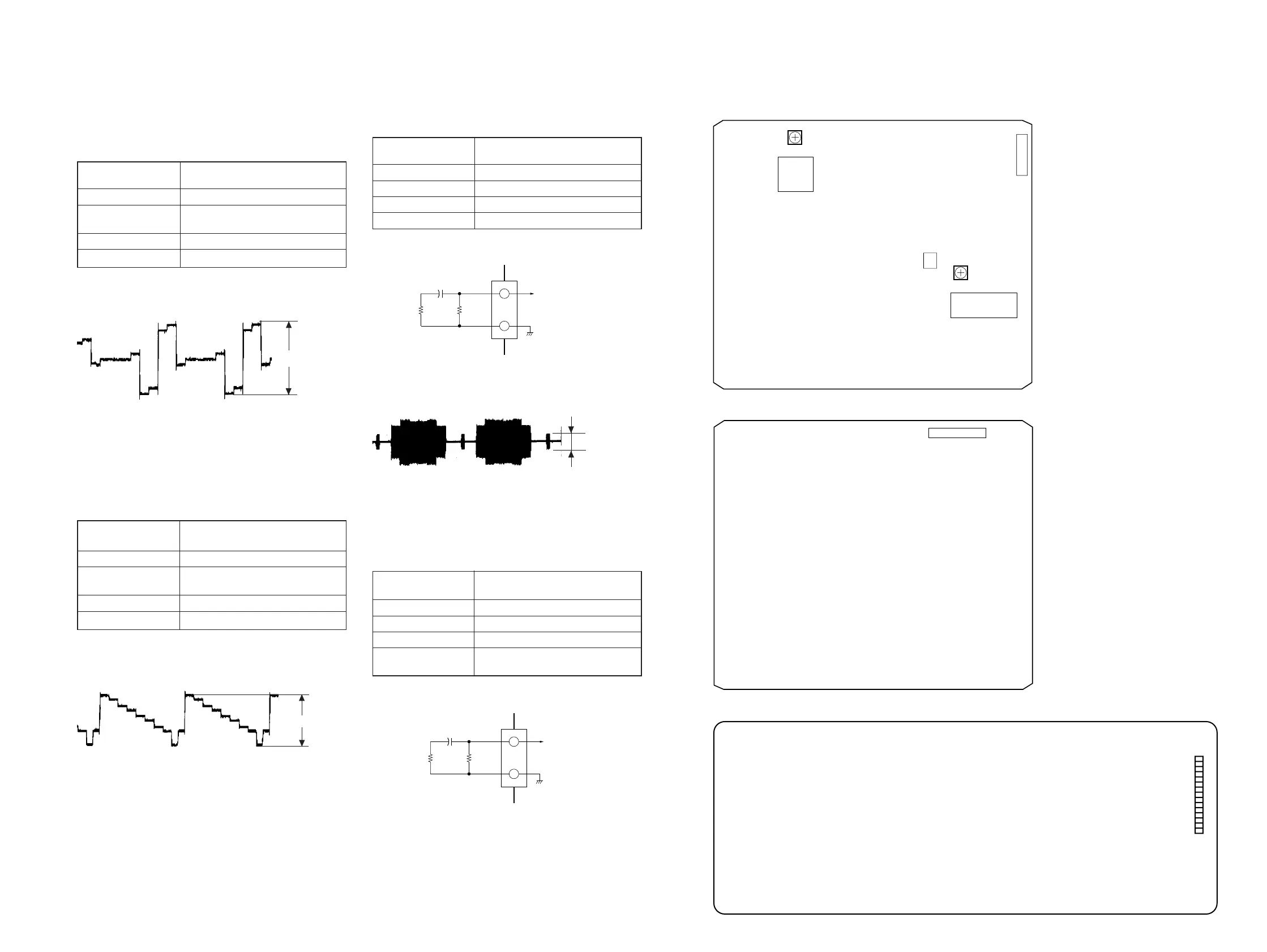
4. Checking Component Video Output R-Y
(MB-84 board)
<Purpose>
This checks component video output R-Y. If it is incorrect, cor-
rect colors will not be displayed when connected to, for instance,
projector.
Mode
Video Encoder (IC252) check in test
mode menu “0” Syscon Diagnosis
Signal Color bars
Test point
COMPONENT VIDEO OUT (R-Y)
connector (75 Ω terminated)
Instrument Oscilloscope
Specification 700 ± 30 mVp-p
Checking method:
1) Confirm that the R-Y level is 700 ± 30 mVp-p.
Figure 7-5
5. Checking Component Video Output Y
(MB-84 board)
<Purpose>
This checks component video output Y. If it is incorrect, correct
brightness will not be attained when connected to, for instance,
projector.
Mode
Video Encoder (IC252) check in test
mode menu “0” Syscon Diagnosis
Signal Color bars
Test point
COMPONENT VIDEO OUT (Y)
connector (75 Ω terminated)
Instrument Oscilloscope
Specification 1 ± 0.05 Vp-p
Checking method:
1) Confirm that the Y level is 1 ± 0.05 Vp-p.
Figure 7-6
6. Checking S Video Output S-C (MB-84 board)
<Purpose>
This checks whether the S-C satisfies the NTSC Standard. If it is
not correct, the colors will be too dark or light.
Mode
Video Encoder (IC252) check in test
mode menu “0” Syscon Diagnosis
Signal Color bars
Test point CN252 !™ pin
Instrument Oscilloscope
Specification 286 ± 20 mVp-p
Connection:
Checking method:
1) Confirm that the S-C burst is 286 ± 20 mVp-p.
Figure 7-7
7. Checking S Video Output DC Level (MB-84 board)
<Purpose>
This checks signals for S1 and S2 compatible TV. If they are not
correct, the TV will not switch automatically to letter box, etc.
Mode
Video Encoder (IC252) check in test
mode menu “0” Syscon Diagnosis
Signal Color bars
Test point CN252 !™ pin
Instrument Digital voltmeter
Specification
S-terminal 0 V: 0 Vdc
S-terminal 5 V: 5.0 Vdc
Connection:
Checking method:
1) In the test mode initial menu “0” Syscon Diagnosis, select S-
terminal 0 V.
Confirm that the voltage at CN252 !™ pin is 0 Vdc.
2) Press any key to select S-terminal 5 V.
Confirm that the voltage at CN252 !™ pin is 5.0 Vdc.
7-4. Adjustment Related Parts Arrangement
MB-84 BOARD (Side A)
+0
–1.5
+0
–1.5
286 ± 20 mVp-p
11
12
100µF
75Ω
±1%
100k
±1%
CN252
+
Digital voltmeter
11
12
100µF
75Ω
±1%
100k
±1%
CN252
+
Oscilloscope
MB-84 BOARD (Side B)
HS-930SU BOARD (Side A)
700 ± 30 mVp-p
1 ± 0.05 Vp-p
RV251
CN251
9
1
VIDEO
LEVEL
ADJ
CT201
IC206
SYS CLK
(27 MHz) ADJ
8
14
7
1
25 1
224
CN252


 To Next Page