7-3
2-4. AUDIO SYSTEM ADJUSTMENTS
• Adjust both Lch and Rch.
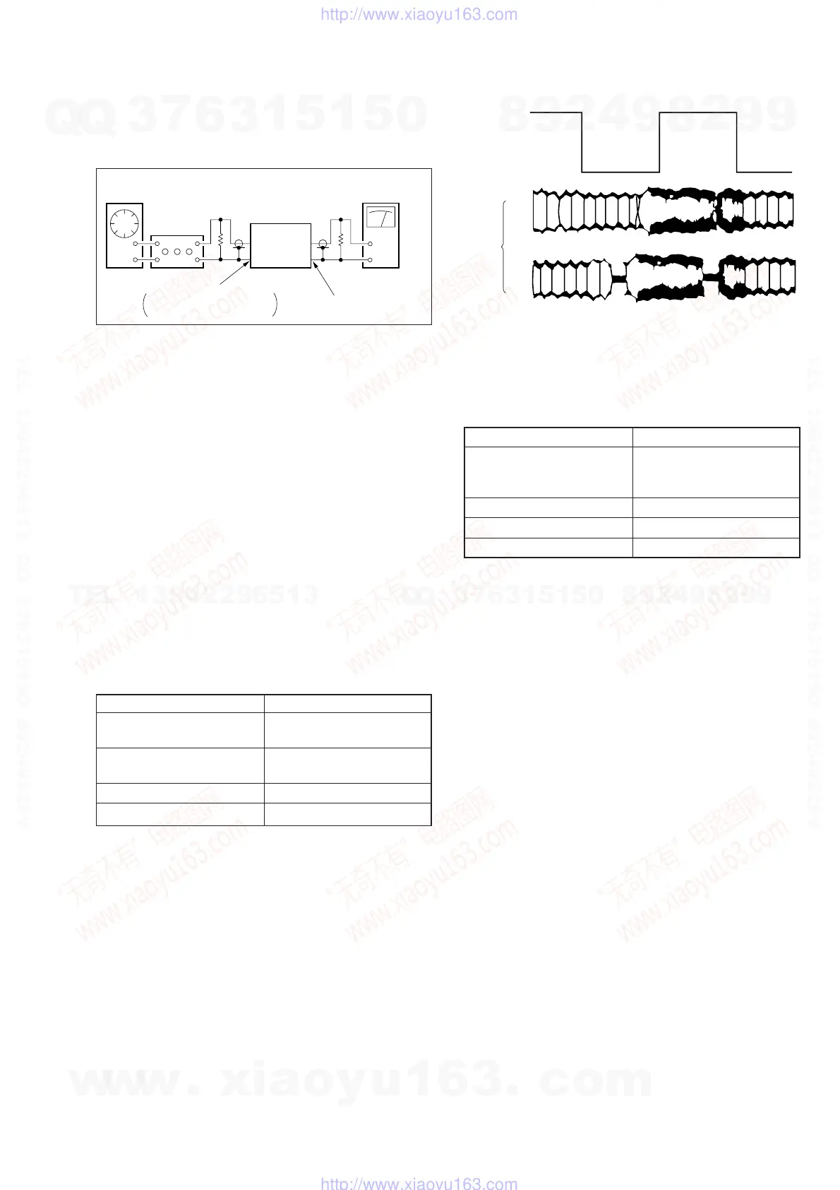
[Connection]
Fig. 7-2-4.
2-4-1. Hi-Fi Audio System Adjustment
(SLV-ED60/ED70/EZ60/EZ70)
• Set switches and knobs to the following positions to make ad-
justment unless otherwise specified.
INPUT SELECT switch ................... LINE
AUDIO MONITOR.......................... STEREO
[Adjustment Sequence]
1. AF Switching Position Adjustment
2. Frequency Response Check
3. Overall Level Characteristic and Distortion Factor
Check
4. Overall S/N Check
1. AF Switching Position Adjustment
(MA-350 BOARD)
Purpose:
Adjust the interval between A CH and B CH of tape playback
output. Improve the interchangeability with other tapes and sets.
When it is out of order, noisy sound is increased and big noise is
heard.
Mode PB
Signal Alignment tape SP mode
color bar
Measurement point CH1: Pin 3 of CN203
CH2: Pin 1 of CN203
Measuring Instrument Oscilloscope
Specified Value Fig. 7-2-5
Adjusting Method:
1) Connect MA-350 board JS450 to the GND for about 1 second
to activate the RF switching position adjustment mode.
2) Press the record button to activate the AF switching position
adjustment mode.
3) Check appear “A H” on FL display.
4) Using the channels + and – buttons, minimize a chipped por-
tion. At this time, confirm that a noisy sound is not heard.
5) Press the pause button.
Fig. 7-2-5.
2. Frequency Response Check
Purpose:
Confirm that the frequency characteristic is within the specifica-
tion.
Mode REC and PB (SP, LP mode)
Signal 400 Hz, –7.5 dBs
20 Hz, –7.5 dBs
20 kHz, –7.5 dBs
Measurement point Audio output terminal
Measurement equipment Audio level meter
Specified value 0 ± 2 dB
Note: Tape path adjustment must have been completed.
Confirmation Method:
1) Supply a signal of 400 Hz, –7.5 dBs to both L and R channels
of Audio Line Input.
2) Connect the audio level meter to the Audio Line Output.
3) Adjust the attenuator so that the audio level meter will indi-
cate –7.5 dBs.
4) Make recording.
5) Set an audio line input signal to 20 Hz and make recording.
6) Set an audio line input signal to 20 kHz and make recording.
7) Playback a recorded portion, and measure output levels at 400
Hz and 20 Hz and 20 kHz.
8) Confirm that the 20 Hz and 20 kHz playback output level within
a range of the 400 Hz playback output level 0 ± 2 dB.
CH2
CH1
RF SWP
OK
NG
Audio
generator
Attenuator
600 Ω
47 kΩ
VCR
Audio level meter or
distortion meter
AUDIO LINE OUT
AUDIO LINE IN
Feed signal both
channelssimultaneously.
w
w
w
.
x
i
a
o
y
u
1
6
3
.
c
o
m
Q
Q
3
7
6
3
1
5
1
5
0
9
9
2
8
9
4
2
9
8
T
E
L
1
3
9
4
2
2
9
6
5
1
3
9
9
2
8
9
4
2
9
8
0
5
1
5
1
3
6
7
3
Q
Q
TEL 13942296513 QQ 376315150 892498299
TEL 13942296513 QQ 376315150 892498299
http://www.xiaoyu163.com
http://www.xiaoyu163.com