14
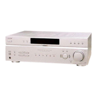
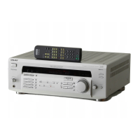
STR-DE485/DE485E
1 DATAO I Serial data input for DIR
2 GP9 I Decode signal input
3 BST O Boot stop signal output to DSP
4 HCS O Chip select signal output to DSP
5 HACN I Acknowledge signal input for DSP
6 XRST O Reset signal output to DSP
7 PM O PLL initialization output to DSP
8 PD O Power down signal output to CODEC
9 SMUTE O Soft mute signal output to CODEC
10 CDT1 O Control data output to CODEC
11 VSS — Ground
12 SCL O Serial data clock to CODEC
13 CS O Chip select signal output to CODEC
14 DATA O Serial data output to VOL/TUNER
15 CLK O Clock signal output to VOL/TUNER
16 LATCH O Latch signal output to VOL/TUNER
17 SPKB O Speaker out control signal output (Not used)
18 HDOUT I Serial data for DSP
19 HDIN O Serial data to DSP
20 HCLK O Clock signal output to DSP
21 F.MUTE O Function input mute signal output
22 AC MUTE O Power amp mute signal output
23 VCC5 I Power supply
24 ANA/DIG I Muting and error port signal input
25 HP DETECT I Headphone detect signal input
26 DCS LED O LED (DCS) driver signal output
27 FLASH2 O Flash programming signal output
28 SP SWITCH/FLASH1 I/O Speaker ON/OFF signal output
29 BLUE LED O LED (MULTI CHANNEL) driver signal output
30 MODE O LED (MODE) driver signal output
31 2CH O LED (2CH) driver signal output
32 AFD O LED (AFD) driver signal output
33 SCL O Clock signal output to EEPROM
34 SDA I/O Serial data to EEPROM
35 AVCC I Power supply
36 AVRH I Not used (connected to “H”)
37 AVSS — Ground
38 to 41 A/D0 to A/D3 I Key signal input (A/D port)
42 VSS — Ground
43 RDS SIGNAL I RDS signal input
44 MODEL I Model detection port
45 VERSION I Version resistor port
46 NC O Not used (connected to ground)
47 NC O Not used (connected to ground)
48 STOP I Input signal when AC off
49 MD0 — Selection of micom operation mode
50 MD1 — Not used (connected to ground)
51 MD2 — Selection of micom operation mode
52 RDS CLOCK I RDS clock signal output (Not used)
53 RDS DATA I RDS data output (Not used)
54 SIRCS I Input data from remote control receiver
55 FUSE DETECT I Power down detect input
• IC1601 MB90478PF-G-120-BND (SYSTEM CONTROL) (DIGITAL Board (2/2))
Pin No. Pin Name I/O Description