EasyManua.ls Logo

Sony STR-DE425 Service Manual

Sony STR-DE425
33 pages
To Next Page IconTo Next Page
Page #1 background imageLoading...
Page #1 background image
STR-DE425
US Model
Canadian Model
AEP Model
UK Model
E Model
Australian Model
Chinese Model
SERVICE MANUAL
FM STEREO/FM-AM RECEIVER
Manufactured under license from Dolby Laboratories
Licensing Corporation.
“DOLBY”, “PRO LOGIC” and the double-D symbol are
trademarks of Dolby Laboratories Licensing Corporation.
MICROFILM
SPECIFICATIONS
Amplifier section
Power output
Stereo mode
(DIN 1 kHz, 4 ohms)
90 W + 90 W
Surround (DIN 1 kHz, 4 ohms)
mode Front: 90W/ch
Centre: 90W
(only in PRO LOG IC MODE)
REAR: (DIN 1 kHZ, 8ohms) 45 W/ch
5.1/DVD Front: 90 W/ch
INPUT * mode (DIN 1 kHz, 4 ohms)
Centre: 90 W (DIN 1 kHz, 4 ohms)
Rear: 45 W/ch (DIN 1 kHz, 8 ohms)
Frequency PHONO: RIAA
response equalization curve ±0.5 dB
TV / LD, CD, TAPE / MD,
VIDEO, 5.1/DVD INPUT:
10Hz - 50kHz ±1dB
Input
Sensitivity Impedance S/N
(Weighting
network,
input level)
PHONO 2.5mV 50 74 dB
(MM) kilohms 72 dB**
(A, 2.5 mV)
CD,
5.1/DVD 200 mV
INPUT*
50 82 dB
TAPE/MD, kilohms 82 dB**
TV/LD, 150 mV (A, 150 mV)
VIDEO
**’78IHF
Outputs TAPE/MD REC OUT:
Voltage: 150 mV,
Impedance: 10 kilohms
VIDEO AUDIO OUT:
Voltage: 150 mV,
Impedance: 10 kilohms
WOOFER/MIX AUDIO
OUT: Voltage: 2V
Impedance: 10 kilohms
PHONES: Accepts low and high
impedance headphones
Muting Full mute
BASS BOOST +10dB at 70 Hz
TONE ±8dB at 100 Hz and 10 kHz
FM tuner section
Tuning range 87.5 – 108.0 MHz
Aerial terminals 75 ohms, unbalanced
Sensitivity Mono: 18.3 dBf, 2.2µV /75 ohms
Stereo: 38.3 dBf, 22.5µV /75 ohms
Usable sensitivity 11.2 dBf, 1V /75 ohms (IHF)
S/N Mono: 76 dB
Stereo: 70dB
Harmonic Mono: 0.3 %
distortion at Stereo: 0.5 %
1 kHz
Separation 45dB at 1 kHz
Frequency 30 Hz – 15kHz
+0.5
dB
response
Selectivity 60 dB at 400 kHz
–2
— Continued on next page —
AM tuner section
Tuning range 531 – 1602 kHz
Aerial Loop aerial
Usable sensitivity 50 dB/m (at 999 kHz)
S/N 54 dB(at 50 mV/m)
Harmonic 0.5%(50 mV/m, 400Hz)
distortion
Selectivity 35 dB
Video section
Input VIDEO 1, 2, TV:
1 Vp-p 75 ohms
Output VIDEO 1, 2, MONITOR:
1 Vp-p 75 ohms
General
System Tuner section; PLL
quartz-locked digital
synthesizer system
Preamplifier section:
Low-noise NF type
epualizer
Power amplifier section:
Pure-complimentary
SEPP
Power 230 V AC, 50/60 Hz
requirements
Power 230 W
consumption
AC outlets Switched 100 W
(except for the U.K.
model)

Other manuals for Sony STR-DE425

Question and Answer IconNeed help?

Do you have a question about the Sony STR-DE425 and is the answer not in the manual?

Sony STR-DE425 Specifications

General IconGeneral
Frequency Response10 Hz - 100 kHz
Weight8.5 kg
Tuning rangeFM
Speaker load impedance8Ω to 16Ω
Video ConnectionsComposite video
Dimensions430 x 145 x 295mm
Speaker Impedance4 - 16 ohms

Summary

Product Specifications

Amplifier and Tuner Specifications

Details power output, frequency response, sensitivities, and S/N ratios for amplifier and tuners.

Video and General Specifications

Covers video signal specs, power requirements, and general unit classifications.

Controls and Connections

Front Panel Controls

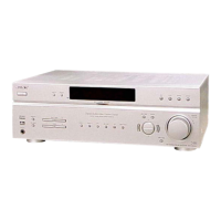
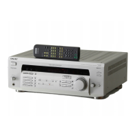
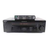
Identifies and describes controls and indicators on the front panel.

Rear Panel Terminals

Lists and describes all input and output connections on the rear panel.

Service Test Modes

Initialization and Indicator Tests

Modes for system initialization, indicator tube test, and software version display.

Configuration and Gain Adjustment Modes

Modes for AM step selection and rear speaker gain adjustment.

System Diagrams and Layouts

Circuit Boards Location

Diagram showing the physical placement of internal circuit boards.

System Block Diagram

Overview of the unit's functional blocks and signal paths.

Schematic Diagrams

Detailed electrical schematics for various functional sections.

Printed Wiring Boards

Layouts illustrating component placement and PCB traces.

Integrated Circuit Details

IC Pin Function Descriptions

Detailed pin assignments and functions for key integrated circuits.

IC Block Diagrams

Internal functional block diagrams for specific integrated circuits.

Exploded Views

Front Panel Assembly Exploded View

Visual breakdown of the front panel components.

Chassis Assembly Exploded View

Visual breakdown of the main chassis and its parts.

Electrical Parts List

Display and Main Board Components

Lists parts for display and main sections: resistors, capacitors, diodes, ICs.

Connectors, Switches, and Miscellaneous Parts

Lists connectors, switches, and other miscellaneous parts from various sections.

Related product manuals