EasyManua.ls Logo

Sony STR-K785 User Manual

Sony STR-K785
52 pages
To Next Page IconTo Next Page
Page #1 background imageLoading...
Page #1 background image
SERVICE MANUAL
Sony Corporation
Home Audio Division
Published by Sony Techno Create Corporation
AEP Model
E Model
Australian Model
MULTI CHANNEL AV RECEIVER
9-887-648-03
2007G16-1
© 2007.07
Ver. 1.2 2007.07
SPECIFICATIONS
STR-K785
STR-K785 is the tuner and the amplifier
section in HT-DDW785 and HTP-78DW.
Manufactured under license from Dolby Laboratories.
“Dolby”, “Pro Logic” and the double-D symbol are trademarks of
Dolby Laboratories.
“DTS” and “DTS Digital Surround” are registered trademarks of
Digital Theater Systems, Inc.
— Continued on next page —
Amplifier section
Power Output
1)
Models of area code SP and SP6
Stereo mode (rated) (6 ohms 1 kHz, THD 1%)
70 W + 70 W
Surround mode
2)
(reference) (6 ohms 1 kHz,
THD 10%)
RMS output
FRONT: 100 W per
channel
CENTER: 100 W
SURROUND: 100 W per
channel
Models of area code AUS
Stereo mode (rated) (6 ohms 120 Hz – 20 kHz,
THD 0.09%)
50 W + 50 W
Stereo mode (rated) (6 ohms 1 kHz, THD 1%)
85 W + 85 W
Surround mode
2)
(reference) (6 ohms 1 kHz,
THD 10%)
RMS output
FRONT: 122 W per
channel
CENTER: 122 W
SURROUND: 122 W per
channel
1)
Measured under the following conditions:
2)
Reference power output for front, center and
surround speakers. Depending on the sound field
settings and the source, there may be no sound
output.
Area code Power requirements
SP, SP6 230 V AC, 50 Hz
AUS 240 V AC, 50 Hz
AEP 230 V AC, 50 Hz
Inputs
Analog Sensitivity: 800 mV/
50 kohms
Digital (Coaxial) Impedance: 75 ohms
Outputs (Analog)
SUB WOOFER Voltage: 2 V/1 kohm
Tone
Gain levels ±6 dB, 1 dB step
Reproduction frequency range:
28 – 20,000 Hz
FM tuner section
Tuning range 87.5 - 108.0 MHz
Antenna FM wire antenna
Antenna terminals 75 ohms, unbalanced
Intermediate Frequency
10.7 MHz
AM tuner section
Tuning range
Stereo mode (rated) (6 ohms, 1 kHz, THD 1%)
85 W + 85 W
Surround mode
2)
(reference) (6 ohms, 1 kHz,
THD 10%) RMS output
FRONT:122 W
per channel
CENTER:122 W
SURROUND:122 W
per channel
Models of area code AEP
With 9-kHz tuning scale:
531 - 1,602 kHz
Antenna Loop antenna
Intermediate Frequency
450 kHz
Video section
Inputs/Outputs
Video: 1 Vp-p, 75 ohms
COMPONENT VIDEO:
Y: 1 Vp-p, 75 ohms
P
B
/C
B
: 0.7 Vp-p,
75 ohms
P
R
/C
R
: 0.7 Vp-p,
75 ohms
80 MHz HD Pass Through
w
w
w
.
x
i
a
o
y
u
1
6
3
.
c
o
m
Q
Q
3
7
6
3
1
5
1
5
0
9
9
2
8
9
4
2
9
8
T
E
L
1
3
9
4
2
2
9
6
5
1
3
9
9
2
8
9
4
2
9
8
0
5
1
5
1
3
6
7
3
Q
Q
TEL 13942296513 QQ 376315150 892498299
http://www.xiaoyu163.com
Question and Answer IconNeed help?

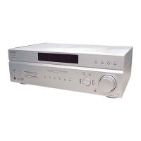
Do you have a question about the Sony STR-K785 and is the answer not in the manual?

Sony STR-K785 Specifications

General IconGeneral
TypeAV receiver
Audio Formats SupportedDolby Digital, DTS
Network ConnectivityNo
Power Output per channel100W
Tuning rangeAM/FM
Speaker load impedance8 Ohm
Video ConnectionsComposite
OutputsRCA

Summary

Specifications

Amplifier Section Specifications

Details power output for stereo and surround modes across different area codes.

FM Tuner Section Specifications

Covers tuning range, antenna type, and intermediate frequency for FM reception.

AM Tuner Section Specifications

Details tuning range, antenna type, and intermediate frequency for AM reception.

Video Section Specifications

Specifies input/output details for video signals, including component video.

General Information

Power Requirements and Consumption

Details power consumption in normal and standby modes for different area codes.

Component Replacement and Safety Notes

Provides guidance on replacing chip components and handling unleaded solder.

Model Identification

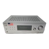
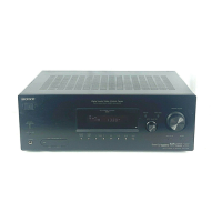
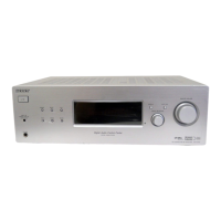
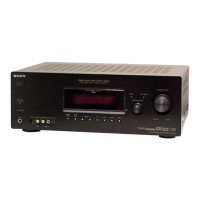
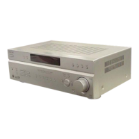
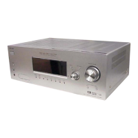
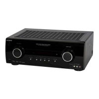
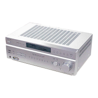
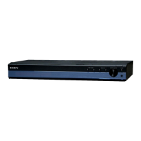
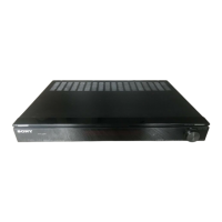
Explains how to identify the model based on the rear panel information.

Diagrams and Circuit Board Layouts

Diagram Notes and Conventions

Explains symbols, abbreviations, and notes used in schematic and PWB diagrams.

Block Diagrams

High-level overview of main sections and display/power systems.

Printed Wiring Boards (PWBs)

Layout diagrams for various circuit boards like Digital, Main, and Video.

Schematic Diagrams

Detailed circuit schematics for Digital, Main, Display, Tuning, Power, and Video boards.

Circuit Board Locations

Illustrates the physical placement of circuit boards within the unit.

4-1. Block Diagram - Main Section

4-2. Block Diagram - Display/Power Section

4-3. Printed Wiring Board - Digital Board (Side A)

4-4. Printed Wiring Board - Digital Board (Side B)

4-5. Schematic Diagram - Digital Board (1/3)

4-6. Schematic Diagram - Digital Board (2/3)

4-7. Schematic Diagram - Digital Board (3/3)

4-8. Printed Wiring Board - Main Board

4-9. Schematic Diagram - Main Board (1/3)

4-10. Schematic Diagram - Main Board (2/3), Headphone Board

4-11. Schematic Diagram - Main Board (3/3), ADCC Board, Standby Board

4-12. Printed Wiring Boards - ADCC Board, Headphone Board

4-13. Printed Wiring Board - Standby Board

4-14. Printed Wiring Board - Display Board

4-15. Printed Wiring Boards - Tuning Board, Power Board

4-16. Schematic Diagram - Display Board, Tuning Board, Power Board

4-17. Printed Wiring Board - Video Board

4-18. Schematic Diagram - Video Board

IC Block Diagrams

Digital Board IC Block Diagrams

Block diagrams for key ICs on the digital board, including IC1131, IC1301, IC1452, IC1401, IC1503.

IC Block Diagrams (Continued)

Main Board IC Block Diagrams

Block diagrams for key ICs on the main board, including IC501, IC601, IC701, IC400.

Video Board IC Block Diagrams

Video Board ICs

Block diagrams for IC251 (NJM2586AL) and IC203 (NJM2279D) on the video board.

Display Board IC Block Diagrams

Display Board ICs

Block diagram for IC100 (PT6315) on the display board.

IC Pin Function Description

Digital Board IC1101 System Control Pinout

Detailed pin function description for IC1101 (MB90488BPF-G-174E1) on the digital board.

Section 5 Exploded Views

5-1. Front Panel Section

Exploded view of the front panel components with part numbers.

5-2. Chassis Section

Section 6 Electrical Parts List

Component Categories

Lists common electrical components like capacitors, connectors, diodes, ICs, jacks, and resistors.

ADCC Board Components

Parts list specific to the ADCC board.

Revision History

Related product manuals