SERVICE MANUAL
Sony Corporation
Home Audio Division
Published by Sony Techno Create Corporation
US Model
Canadian Model
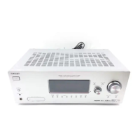
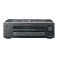
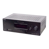
STR-K900
AEP Model
UK Model
E Model
Australian Model
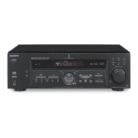
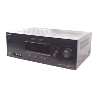
STR-K880
MULTI CHANNEL AV RECEIVER
9-887-101-02
2006E16-1
© 2006.05
Ver. 1.1 2006.05
SPECIFICATIONS
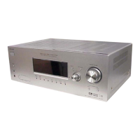
STR-K880/K900
• STR-K880 is the tuner and the amplifier section
in HT-DDW880, STR-K900 is the tuner and the
amplifier section in HT-DDW900.
Manufactured under license from Dolby Laboratories.
“Dolby”, “Pro Logic” and the double-D symbol are trademarks of
Dolby Laboratories.
“DTS” and “DTS Digital Surround” are registered trademarks of
Digital Theater Systems, Inc.
— Continued on next page —
POWER OUTPUT AND TOTAL
HARMONIC DISTORTION:
(Models of area code U
S only)
With 6 ohm loads, both channels driven, from
120 – 20,000 Hz; rated 90 watts per channel
minimum RMS power, with no more than
0.7% total harmonic distortion from 250
milliwatts to rated output.
Amplifier section
Power Output
1)
Models of area code US, CND
(6 ohms 1 kHz, THD 0.7%)
FRONT
2)
: 90 W/ch
CENTER
2)
: 90 W
SUR
2)
: 90 W/ch
(6 ohms 1 kHz, THD 10%)
FRONT
2)
: 140 W/ch
CENTER
2)
: 140 W
SUR
2)
: 140 W/ch
1)
Measured under the following conditions:
2)
Depending on the sound field settings and the
source, there may be no sound output.
Inputs (Analog)
Area code Power requirements
US, CND 120 V AC, 60 Hz
MULTI CH IN,
SA-CD/CD,
MD/TAPE, DVD,
VIDEO 1, 2, 3
Sensitivity: 800 mV
Impedance: 50 kohms
Models of area code AEP, UK, SP, SP6, E51
(6 ohms 1 kHz, THD 0.7%)
FRONT
2)
: 90 W/ch
CENTER
2)
: 90 W
SUR
2)
90 W/ch
SUR BACK
2)
: 90 W
(6 ohms 1 kHz, THD 10%)
FRONT
2)
: 135 W/ch
CENTER
2)
: 135 W
SUR
2)
:
:
135 W/ch
SUR BACK
2)
: 135 W
Models of area code AUS
(6 ohms 120 Hz – 20 kHz, THD 0.09%)
FRONT
2)
: 70 W/ch
CENTER
2)
: 70 W
SUR
2)
: 70 W/ch
SUR BACK
2)
: 70 W
(6 ohms 1 kHz, THD 0.7%)
FRONT
2)
: 90 W/ch
CENTER
2)
: 90 W
SUR
2)
: 90 W/ch
SUR BACK
2)
: 90 W
(6 ohms 1 kHz, THD 10%)
FRONT
2)
: 135 W/ch
CENTER
2)
: 135 W
SUR
2)
: 135 W/ch
SUR BACK
2)
: 135 W
AEP,UK,SP,SP6 230 V AC, 50 Hz
E51, AUS 240 V AC, 50 Hz
Inputs (Digital)
Outputs (Analog)
DVD (Coaxial) Sensitivity: –
Impedance: 75 ohms
VIDEO 1, 2
(Optical)
Sensitivity: –
Impedance: –
MD/TAPE (OUT),
VIDEO 1 (AUDIO
OUT)
Vo lt age: 800 mV
Impedance: 10 kohms
SUB WOOFER Voltage: 2 V
Impedance: 1 kohm
Photo : STR-K880