EasyManua.ls Logo

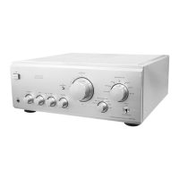
Sony TA-FA777ES - Disassembly Procedures; Front Panel and Main Board Disassembly; Sub Chassis and Function Switch Board Disassembly

Sony TA-FA777ES
24 pages
Print Icon
To Next Page IconTo Next Page
To Previous Page IconTo Previous Page
Loading...
4
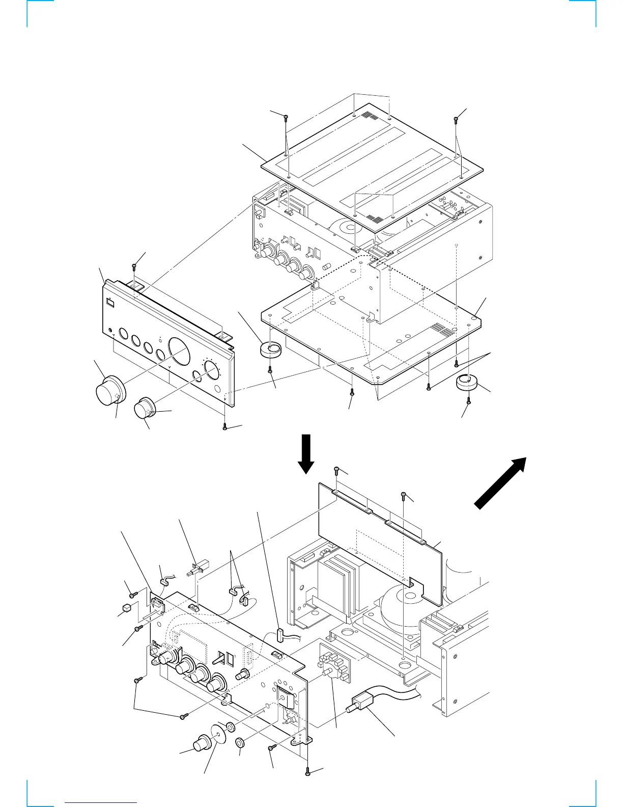
FRONT PANEL, TOP board, BOTTOM board
SUB CHASSIS, FUN-SW BOARD
Note: Follow the disassembly procedure in the numerical order given.
SECTION 2
DISASSEMBLY
8
three screws
(BV 3
×
8)
0
two screws
(B 4
×
20)
qs
three screws
(BV 3
×
8)
0
three screws
(B 4
×
20)
qa
three foots
qs
five screw
s
(BV 3
×
8)
qd
bottom board
1
four screws
(FLAT HEAD)
1
four screws
(FLAT HEAD)
2
top board
qa
two foots
7
two screws
(BV 3
×
8)
9
front panel
6
knob (DIA.68)
5
screw
3
screw
4
knob (DIA.48)
5
sub chassis
1
two screws
(BV 3
×
8)
2
shield plate
1
four screws
(BV 3
×
8)
qd
rotary switch
(remote type)
4
four screws
(BV 3
×
8)
qg
FUN-SW board
4
two screws
(BV 3
×
8)
qf
nut
qa
light interception sheet (B)
0
knob (DIA.29)
4
four screws
(BV 3
×
8)
4
screw
(BV 3
×
8)
7
power botton
assy
8
two screws
( 3
×
6)
9
switch, push
(AC power)
3
connector
(CN806)
6
two connectors
(CN807, 808)
qh
connector
(CN304)
qs
nut