Do you have a question about the Sony TA-FB920R and is the answer not in the manual?
Details on power output, harmonic distortion, frequency response, S/N ratio, impedance, and damping factor.
Covers system type, power requirements, consumption, dimensions, mass, and supplied accessories.
Identifies model variations (AEP, UK, etc.) and associated part numbers for the back panel.
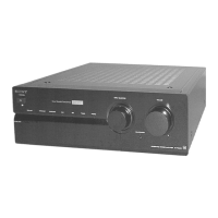
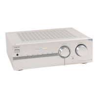
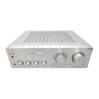
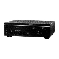
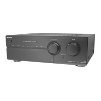
Identifies and describes the function of each control and indicator on the front panel.
Identifies and describes the function of each connector and control on the rear panel.
Step-by-step procedure for performing the bias adjustment, including necessary tools and locations.
Illustrates the location and names of all circuit boards within the device for reference.
Provides the detailed electrical schematic diagram for the input signal processing section.
Shows the component layout on the printed wiring board for the input section.
Provides the detailed electrical schematic diagram for the main amplifier section.
Shows the component layout on the printed wiring board for the main section.
Provides the detailed electrical schematic diagram for the front and rear panel control circuits.
Shows the component layout on the printed wiring board for the panel section.
Provides the detailed electrical schematic diagram for the power supply and transformer circuits.
Shows the component layout on the printed wiring board for the power supply section.
Visual representation of the functional blocks within key integrated circuits.
Details the pin assignments and functions for specific integrated circuits.
Illustrates the assembly and parts breakdown of the unit's case and back panel.
Illustrates the assembly and parts breakdown of the unit's front panel components.
Illustrates the assembly and parts breakdown of the unit's chassis and internal components.
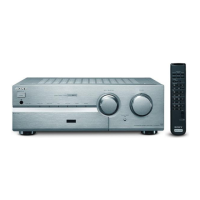
Lists included accessories like remote control and instruction manuals in various languages.
Lists various screws and fasteners used in the assembly of the unit.